Table of Contents
Advertisement
Quick Links
Advertisement
Table of Contents
Troubleshooting

Related Manuals for Cincinnati 90 FORM MASTER II


Summary of Contents for Cincinnati 90 FORM MASTER II
- Page 1 C I N C I N N A T I I N C O R P O R A T E D C I N C I N N A T I , O H I O 4 5 2 1 1 COPYRIGHT 1999 EM-407 (R-06/99) CINCINNATI INCORPORATED...
-
Page 2: Table Of Contents
FORM MASTER II PRESS BRAKE CONTENTS INTRODUCTION SECTION 1 IDENTIFICATION SECTION 2 INSTALLATION UNLOADING LIFTING AND MOVING FOUNDATION ERECTION CLEANING LEVELING HYDRAULIC RESERVOIR LUBRICATION ELECTRICAL CONNECTION(S) RS-232 COMMUNICATIONS INSTALLATION TROUBLESHOOTING CONFIGURATION (1) SECTION 3 SAFETY SAFETY RECOMMENDATIONS FOR SAFE OPERATION OPERATING RULES GUIDELINES FOR INSTALLING / REMOVING TOOLING SAFETY SIGNS... - Page 3 SECTION 6 MACHINE CONTROLS FORM MASTER II CONTROL STATION PALMBUTTON OPERATOR STATION FOOTSWITCH FORM MASTER II ELECTRICAL ENCLOSURE CONTROLS - FORM MASTER II OPTIONS ADDITIONAL OPERATOR CONTROLS CNC BACKGAGES RS-232 CONVENIENCE PORT 6-10 POWER CLAMPS 6-10 SECTION 7 OPERATION DAILY START-UP POWER-DOWN MACHINE CALIBRATION ENTERING A NEW PROGRAM...
- Page 4 CNC PLATE GAGE (Optional) 9-11 CARRIAGE ADJUSTMENT 9-12 MAINTENANCE CHECKLIST 9-12 TROUBLESHOOTING 9-13 VFD DISPLAY ERROR MESSAGES 9-15 SECTION 10 SERVICE AND PARTS ORDERING REPAIR PARTS 10-1 RETURNING PARTS FOR CREDIT 10-1 SERVICE 10-1 TECHNICAL TRAINING 10-1 COPYRIGHT 1999 CINCINNATI INCORPORATED...
- Page 5 Selecting the proper bend sequence is important to obtain quality parts and for operator safety. CINCINNATI offers both Operator and Maintenance training programs at our factory to address these factors. This training may cover subjects from the basics of forming to the use of the machines' microcom- puter controls.
-
Page 6: Identification
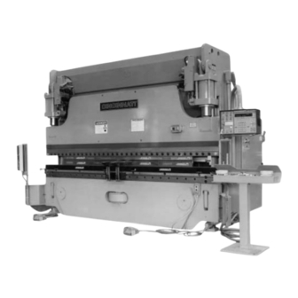
SECTION 1 IDENTIFICATION FORM MASTER II PRESS BRAKE LEFT HOUSING 10. MAIN DISCONNECT SWITCH 17. BACKGAGE BAR (Optional) CYLINDER MANIFOLD & VALVES (2) 11. CAPACITY PLATE 18. PRESENCE SENSING GUARD ON - OFF LIGHTS (Optional) COUNTERBALANCE MANIFOLD AND 12. PRESENCE SENSING DEVICE VALVES (2) 19. - Page 7 FORM MASTER II PRESS BRAKE ENCODER GUARD OIL SIGHT GAGE AND THERMOMETER HOUSING BRACE / HYDRAULIC RESERVOIR CNC HEAVY DUTY BACKGAGE with PROGRAMMABLE DRIVE MOTOR AND PUMP R-AXIS (Optional) OIL FILTER LEVELING SCREW (4) RESERVOIR DRAIN VALVE FIGURE 1 - 2 – Rear View...
-
Page 8: Installation
If short cables are used, fit a spreader beam between the housings near the lifting holes. A typi- A CINCINNATI FORM MASTER II must be provided cal hitch is shown in Figure 2-1. with a rigid foundation to ensure that alignment of... -
Page 9: Erection
The encoder lower mounting brackets were removed Remove the grease with a clean rag soaked in sol- for shipment. A CINCINNATI INCORPORATED Ser- vent, such as mineral spirits, wipe with clean rags. vice Representative will install and adjust the A stiff brush will get into the corners. -
Page 10: Leveling
This is done by loosening the ram clamp bolts until the ram CINCINNATI FORM MASTER II is leveled by plac- hangs free of the guides. Measure with a feeler gage ing flat steel shims (supplied with machine) of... -
Page 11: Hydraulic Reservoir
A ground lug on the line side of the machine main for your CINCINNATI FORM MASTER II. disconnect is provided for this purpose. Refer to local and state codes for acceptable grounding methods. -
Page 12: Installation
FIGURE 2 - 5 – Cable connections Check the jumpers on the cable ends. COMMUNICATIONS PROTOCOL Switch the wires on pins #2 and #3 and retest. 1. Communications Protocol used by CINCINNATI Check the MSKERMIT.INI file. See the following: VME Controls is "KERMIT". Applications sup-... -
Page 13: Configuration
MS-DOS Kermit V2.29 or higher (kermit is a 4:*SET PORT 1 <ENTER or RETURN> public domain communications protocol used (This is the port used on the PC) by the CINCINNATI INCORPORATED (VME) 5:*SET BAUD 9600 <ENTER or RETURN> Control. (This is the speed of information transfer) 6:*SET FILE TYPE BINARY <ENTER or RETURN>... - Page 14 (This will put you into SERVER MODE if the “MSKERMIT.INI” has been set-up as shown pre- MS-KERMIT>STATUS <ENTER or RETURN> viously.) (This will give more complete setting information) CLIENT SERVER KERMIT CINCINNATI MACHINE 256K MEM 1.2/1.44 FLOPPY 10M Harddsk Male DB-25 RS232 9600 baud...
-
Page 15: Safety
(See ANSI B11.3.) CINCINNATI INCORPORATED recommends you If you use two-hand operator control station(s) as read and understand the safeguarding, use and... -
Page 16: For Safe Operation
The CINCINNATI FORM MASTER II you are operat- 7. Protect your eyes from flying particles of metal ing will not produce a tonnage greater than the by always wearing your safety glasses. -
Page 17: Safety Signs
If the punch or die has tapped holes for lifting of tooling from your CINCINNATI Press Brake. attachments, be sure the proper size bolts are used. A bolt smaller in diameter than the... -
Page 18: Safety Guidelines
This DANGER sign warns operators to keep their TURN OFF OR LOCKOUT OPERATOR CONTROLS TURN POWER OFF hands out of the die area (point-of-operation). The DO NOT REMOVE THIS SIGN FROM THIS PRESS BRAKE 240003 sign is usually attached to one end of CINCINNATI... -
Page 19: Safety Maintenance Check
GUARD AGAINST TIPPING Make certain all persons are clear of machine and material before operating The design of hydraulic press brakes is such that When you leave your press brake: much of the weight is concentrated to the front of the machine. -
Page 20: Specifications
SECTION 4 SPECIFICATIONS PERFORMANCE AND RATINGS SHIPPING WEIGHT CLEAR TOTAL BENDING CAPACITY BED TOP DISTANCE OVERALL (Mild Steel) LENGTH FMII AUTO CROWN ABOVE MOTOR BETWEEN ADDITIONAL SERIES REQD. FLOOR WIDTH Ft.-Nominal H.P. BACKGAGE) HOUSINGS SURFACE WEIGHT GA. x FT. (kw) Lbs. -
Page 21: Specifications Chart
MACHINE CAPACITY THROAT DIE SPACE RAM SPEED OVERALL STD. CLEARANCE Inches Inches/Min. HEIGHT MAX. SPEED MAX. TONNAGE STROKE FROM CENTER (mm) (mm/Sec.) ABOVE AT FULL AT FULL SERIES LENGTH OF DIES FLOOR TONNAGE FORM. SPEED Inches Inches Inches OPEN CLOSED HIGH VARIABLE Inches/Min. - Page 22 CLOSED POSITION: This is the overall height of ity. Also see the CINCINNATI Press Brake Capac- the dies when ram is at the bottom of the stroke ities booklet PT-50691 included with the com- and is adjusted to make the proper bend.
-
Page 23: Capacities
Figure 4-6 shows the maximum stripping load available at the center CAPACITIES of the machine. PUNCHING CAPACITY FORM MAXIMUM CINCINNATI Hydraulic Press Brakes are rated to MASTER STRIPPING LOAD perform punching loads up to 66% of the maximum TONS (kN) SERIES... -
Page 24: Off-Center Load Capacity (L-R)
For example, a 135FM II Press Brake has 100% - ! ! DANGER ! ! ! ! DANGER ! ! 135 tons (1201kN) of its rating available for bend- ing at the centerline of the machine. At either hous- EXCEEDING THE ECCENTRIC LOAD CAPACITY ing, regardless of length, only 50% of the tonnage - COULD OVERSTRESS UPPER BED AND DIE 67.5 tons (600.5kN) is available. -
Page 25: Set-Up And Use
SECTION 5 SET-UP & USE PRESS BRAKE TOOLING These dies, being the most common and widely used, will be referred to in the following instructions. A hydraulic press brake is a very versatile bending machine. It is capable of exerting high forces TYPES OF DIES between its bed and ram. -
Page 26: Tool Installation
CINCINNATI INCORPORATED can provide many TOOL INSTALLATION other types of standard and special dies, some of To install the tooling, use the following procedure: which are shown in Figure 5-4. Turn “ON” the main disconnect switch. Depress MAIN DRIVE - START pushbutton on FORM MASTER II Control Station (Figure 6-1). - Page 27 If the ram is not at maximum "up" position, the unclamped position. Depress RAM JOG but- ton and turn the OPERATOR CONTROLS selec- depress RAM UP button on Palmbutton Opera- tor to “ON”. tor Station to raise ram. Ram will move to max- imum "up"...
-
Page 28: Gaging - Optional Backgages
IMPORTANT: When seating dies it may be advisable GAGING - OPTIONAL BACKGAGES to place wood blocks or soft metal between the dies to prevent damage to the dies. Short dies There are three types of Optional Backgages must have sufficient shoulder area to prevent available on the FORM MASTER II. -
Page 29: Adjust Gage Finger Position
Two pairs of gage fingers are furnished with each generally recommended for gaging large sheets or backgage. The 1" (25mm) gage finger or the 1/4" plates over 100 lbs. (45.4kg). (6.4mm) gage finger is installed into the gage The face of the gage fingers is the contact surface, assembly as shown in Figure 5-9. - Page 30 24" .25" 8" FINGER SIZE 1" .125 (25.4mm) (6.4mm) (3.2mm) 2" 1.125 .438 .313 (6.4) (28.6) (11.1) .375 1.188 .375 (9.5) (30.2) (12.7) (9.5) 1.25 .563 .438 FIGURE 5 - 13 – Adjusting gage surfaces (12.7) (31.8) (14.3) (11.1) .625 1.313 .625 The gage finger assemblies should be positioned...
-
Page 31: Program Gage Positions(S)
Minor part flange differences (end-to-end) can be corrected by adjusting the individual gage fingers either forward (to shorten flange) or backward (to – lengthen flange). First remove the gage assembly from the backgage bar. Loosen the finger by pulling out the locking knob (Figure 5-8) and turning knob counterclockwise. -
Page 32: Operating Techniques
droop away from the gage surface) are formed. 75° (or less) dies when 90° air bending for cer- These supports attach to rear dovetail slots in the tain materials with large “springback”. See Fig- bed and should be positioned at same height as the ure 5-18. -
Page 33: Speed Change/Forming Speed
DO remove burrs or keep burrs up on material Set the controls on the FORM MASTER II Con- trol Pendant Station. Turn the MODE SELECT for more consistent bends. switch to "SET-UP" position and the OPERA- DO run production in same speed in which the TOR STATION - RIGHT to "ON". -
Page 34: Machine Controls
SECTION 6 MACHINE CONTROLS The FORM MASTER II is a multi-axis microcom- erally determined by the part(s) being formed and tooling used. Keylock selector switches are provided puter controlled programmable system. The stan- for use by supervisory or set-up personnel to main- dard single-axis is the vertical motion of the ram. - Page 35 MACHINE CONTROL STATION MODE SELECT Switches: Two keylock switches are used to select the stroking mode. The first 3- OPERATOR STATION RIGHT (or LEFT) Selector: position switch has “OFF”, “SET-UP”, “SINGLE One Operator Station is furnished as standard STROKE” and optional RUN mode positions. In equipment and is usually connected to the "SINGLE STROKE"...
-
Page 36: Form Master Ii Control Station
“SINGLE STROKE PALMBUTTONS buttons the OPERATOR STATION selector switch FOOTSWITCH” - This is a production mode that on FORM MASTER II Control Station (Figure 6-1) can be operated by the palmbuttons, footswitch or must be turned “ON” and the FOOTSWITCH a combination of palmbuttons and footswitch. - Page 37 Note: If a machine fault should occur during operation, CAUTION it is recommended that power is turned off by pressing the EMERGENCY STOP button on the THE OPERATOR SHOULD LOCK THIS SWITCH Operator Station (Figure 6-4). "OFF"AND REMOVE KEY WHEN AWAY FROM THE MACHINE OR WHEN PERFORMING VFD Display: ADJUSTMENTS TO PREVENT ANYONE FROM...
- Page 38 COMMUNICATION (F) Key: open height. The default for Bottom Position is the machine open height. This key is labeled "OFFLINE" and is used to initi- ate RS-232 data transfers. For more information on Dwell Time - The period of time that the ram offline communication, see “OFFLINE COMMUNICA- stops (dwells) at the bottom position at stroke TION”...
- Page 39 Low Return Speed - The speed in inches/minute Disable Backgage: This function is used to allow (mm/sec) the ram travels after bottom reversal the FORM MASTER II to be cycled when the on the Up Stroke until the ram passes through backgage is removed or malfunctioning.
- Page 40 through or stops at the Clamp Position, or when CLR (Clear) Key: If numerical inputs have been the ram stops at the top position. The Retract made in error, depressing the "CLR" key will Distance allows the backgage to retract so a erase the entry line only and new data may be reverse flanged part will clear the gage surface entered.
-
Page 41: Palmbutton Operator Station
press the "NEXT" key. It is necessary to depress must be pressed about the same time to start and hold down on the footswitch as you press on ram motion. The palmbuttons will cycle the ram the "Jog Up" and "Jog Down" softkeys to get the in all modes of operation except “SINGLE ram to move. -
Page 42: Footswitch
FOOTSWITCH IMPORTANT: This 10-15 second delay is required to allow machine functions to reset properly. This is a guarded, three-position operator control which controls ram motion. It can be used in all POWER SUPPLIES OPERATIONAL Light: Indi- “SINGLE STROKE” modes of operation. The ram cates all internal power supplies are operating will move when the footswitch is held depressed. -
Page 43: Rs-232 Convenience Port
RS-232 CONVENIENCE PORT The RS-232 Convenience Port is a hardware option that provides a pre-wired DB-25 RS-232 connector R-AXIS in a covered box on the outside of the main electri- cal enclosure. See "RS-232 INSTALLATION" in SEC- X-AXIS TION 2 for cable connections and protocol. POWER CLAMPS Power clamps provide means to rapidly install or remove tooling. -
Page 44: Operation
SECTION 7 OPERATION DAILY START-UP 6. Depress palmbuttons and move ram down until the dies are just touching, or if the dies are removed, replace them with blocks. At the beginning of a new shift, after every break, at the start of a new job, or when the press is started 7. -
Page 45: Entering A New Program
CINCINNATI INCORPORATED FORM MASTER II SET-UP SHEET towards the limit switches. When the ram hits SPECIAL INSTRUCTIONS DATE PART NO. the limit switches, the ram stops. There will be SHEET JOB NO. a slight pause and then the ram will move back PREPARED BY up to the reference point and stop. -
Page 46: Programming
(90° - 10° -5° = 75°). 4. Vee openings and upper die radii should follow Press the "YES/+" key and the following screen will the guidelines recommended in CINCINNATI be displayed: INCORPORATED's booklet "Press Brake Capac- ities, PT-50691". For mild steel, the vee open-... - Page 47 For this example enter a vee opening of 0.50": ENTER MAT. THICKNESS 0.000 The display should now read: This dimension should be measured to the nearest .001" (0.03mm). For this example program enter a thickness of .060": VEE OPENING 0.500 ENTER LOWER VEE DIE ANGLE To enter the lower vee die angle, press either the...
- Page 48 The easiest and recommended way to enter this This concludes entering the necessary material and dimension is to move the ram down in RAM JOG tool dimensions. Pressing the "ENTER NEW PRO- mode until the upper die just touches a sample GRAM"...
- Page 49 Note that the actual angle returns to the default ENTER value (the desired angle) and the total correction is updated. Press the "BOTTOM POSITION" key until the bottom position screen is displayed. The display Press the "BOTTOM POSITION" key until the bot- should read: tom position screen is displayed.
-
Page 50: Ram Programming
RAM PROGRAMMING The Top Stop Position can also be selected by using the RAM JOG mode to position the ram at the TOP POSITION desired top stop location, then selecting the TOP STOP POSITION function and using the TRANSFER function to transfer the current actual ram position (shown in the upper left quadrant of the display for POSITION the TOP STOP POSITION.) See "OPERATING TECH-... -
Page 51: Speed Change Position
Enter the lower tool name "L1": UP SPEED CHANGE Next select the UP SPEED CHANGE function by STEP 1 pressing the multi-function "SPEED CHANGE" key until the display reads: LOWER TOOL: L1 POS: XX.XXXX STEP 1 SPEED CHANGE POSITION UP SPEED CHNG XX.XXXX SPEED CHANGE... -
Page 52: Programmable Output (Optional)
PROGRAMMABLE OUTPUT (Optional) POS: XX.XXXX STEP 1 The FORM MASTER II has an optional output OUTPUT ON AT 14.0000 which can be used to control auxiliary equipment. This output controls a relay with normally open and normally closed contacts. When the ram reach- OUTPUT "OFF"... -
Page 53: Dwell Time
tion must be entered numerically. Press the multi- POS: XX.XXXX STEP 1 function “BOTTOM POSITION” key. The display should now read: DWELL TIME POS: XX.XXXX STEP 1 The Control is now in the DWELL TIME data entry mode with the flashing cursor under the first digit BOTTOM POS. -
Page 54: Programmable Footswitches (Optional)
The display now reads: PROGRAMMABLE FOOTSWITCHES (Optional) This option can be used to select which footswitch POS: XX.XXXX STEP 1 (right, left, or both) must be pressed to cycle the RAM TILT 0.0000 ram when two footswitches are installed. To turn the Programmable Footswitch Option ON, press the "RAM TILT"... -
Page 55: Stroke Stops
SPEED CHANGE DOWN position. This is used WARNING - FOOTSWITCHES when the operator must align the material just before bending or when using the HAND/FOOT ARE PROGRAMMABLE ! combination of control. To restart ram motion, palmbuttons or footswitch must be released and re- activated. -
Page 56: Ram Speed
For this example, use a forming speed of 15 inches per minute: The display should now read: ENTER UP STOP ON STEP 1 The display should now read: TURN OFF? POS: XX.XXXX STEP 1 For this example program, turn the UP STROKE FORMING SPEED STOP off: LOW RETURN SPEED... -
Page 57: Cycles Per Step
REVERSAL TONNAGE The Control is now in the TONNAGE MODE func- tion. The tonnage mode default is “NO”. Select the REVERSAL TONNAGE function by press- ing the multi-function “TONNAGE” key. The display With the tonnage mode set to “NO”, the ram revers- should read: es at the bottom position as long as the tonnage does not exceed the value programmed for the... -
Page 58: Guard Mute Position (Optional)
Note: If the display shows the PARTS COUNT func- Note: If using ANGLE mode, the Guard Mute position tion, press the multi-function “CYCLES PER defaults to 1/4" above the top of material. STEP” key again to select the CYCLES PER The guard mute position is the point in the down STEP function. -
Page 59: Independent Gage Mode (Optional)
Note: If the display shows the CLAMP STOP OR When the Independent Mode is enabled, both left DISABLE GAGE functions, press the GAGE and right gage positions must be programmed. PROGRAM “FUNCTION” key until the display When the Independent Mode is disabled, a flange shows the GAGE PAUSE TIME function. -
Page 60: Disable Backgage
DISABLE BACKGAGE The Control is now in the FLANGE DIMENSION data entry mode with the flashing cursor under the Select the DISABLE BACKGAGE function by press- first digit of the flange dimension. The default ing the multi-function GAGE PROGRAM “FUNC- FLANGE DIMENSION is a maximum gage dimen- TION”... -
Page 61: Bend Allowance
The Control is now in the CLAMP POSITION data POS: XX.XXX STEP 1 entry mode with the flashing cursor under the first digit of the clamp position. The default clamp posi- R AXIS POS 7.100 tion is zero inches, which disables the CLAMP POSITION and CLAMP STOP function. -
Page 62: Editing A Program
grammed clamp position. If the ram reaches the POS: XX.XXXX STEP 2 bottom of the stroke before the clamp position, the gage will ignore the retract position. TOP POS 14.5000 When a step is inserted, all the data from the cur- rent step is copied and used to form the new step. -
Page 63: Calculator Mode
The display should now read: The display will read: INSERT A STEP AFTER DELETE CURRENT STEP THE CURRENT STEP? ARE YOU SURE? The “YES/+” key deletes the step, and any other This prompt will appear whenever a step is insert- key aborts the step deletion. -
Page 64: Program Memory
The display now reads: at this point. A one to eight character name is entered using the number keys and/or the “YES/+” and “NO/-” keys until the desired character is POS: XX.XXX STEP 2 flashing, then press the “TRANSFER” key to select FLANGE DIMEN 4.770 the character. -
Page 65: Deleting A Program
The display should read: FILE LIST: NNNNNNNN BYTES LEFT XXXXX PGM: 255 RECALL COMPLETE The “YES/+” and “NO/-” keys can be used to dis- play the programs stored in Program Memory one at a time. If no programs are stored, the display will DELETING A PROGRAM read: To delete a program from Program Memory, press... -
Page 66: Offline Communication
To receive a file from a remote “KERMIT” server, CYCLE ACTIVE! STEP XX press the multi-function “OFFLINE” key until the display reads: LOAD XXX FLANGE XX.XXX RECEIVE PROGRAM The display shows the current step number, the ENTER PGM: load that the previous stroke required, and the flange dimension of the current step. - Page 67 The name of the program to be sent can be entered or the “NEXT” key can be used to list (one at a time) User Host Command: the programs in Program Memory sorted alphabet- ically. If “*” is entered as the file name, all programs currently stored in the press will be sent, one at a time, to the offline server.
- Page 68 RS-232 TEST RS-232 TEST RCV ERR! A jumper wire should be connected between pins 2 This process may be repeated with the jumper at and 3 of the presses RS-232 port. To start the test, various points on the cable. This allows the cable to press the “ENTER”...
-
Page 69: Options
With this device, the bend angle remains IMPORTANT: Do not make any electrical connections constant along the nominal length of the bed. or final adjustments until a CINCINNATI INCOR- PORATED Service Representative is present. A machine equipped with Auto Crown does not In the event that the gage is not already assembled have a microcrowned bed. -
Page 70: Cnc Heavy Duty Backgage
ment. The CNC Backgage is designed for sheets up The backgage is designed for sheets up to 1/4" to 3/16" (3.8mm) maximum thickness that weigh (6.4mm) thickness that weigh less than 150 lbs. less than 100 lbs. (45.4kg). It can be provided on (68kg). -
Page 71: Manual Front Gages
They are immersion-type tion for a supervisory keyed switch is plugged. Con- and are thermostatically controlled. The oil heaters tact CINCINNATI INCORPORATED if totally dis- may be used independently of the motor drive. It abling the Interface is required. -
Page 72: Programmable Footswitch
PRESENCE SENSING PROGRAM MUTE POSITION FIGURE 8 - 8 – Presence Sensing Device PROGRAMMABLE FOOTSWITCHES 827190 Programmable Footswitches is an available option on the FORM MASTER II Control. It may be used FIGURE 8 - 7 – Presence Sensing Control Panel to select which footswitch (left, right or both) must be pressed to cycle the ram when two footswitch- es are installed. -
Page 73: Lubrication
SECTION 9 MAINTENANCE & ADJUSTMENTS To maintain the accurate performance of your CNC BACKGAGE (Optional) CINCINNATI FORM MASTER II Hydraulic Press Brake, there are maintenance practices that should be followed. This section deals with the mainte- nance and adjustments of the Press Brake. - Page 74 If, for any reason, lubrication becomes necessary, contact CHANNEL LEVELING the Service Department of CINCINNATI INCOR- FOOT PORATED. Optional Power R-axis. Raise the R-axis to the maximum up position. This will expose a lubrica- tion access hole in the back of the vertical guide tube.
-
Page 75: Hydraulic Oil
0°C will require additional measures to protect hydraulic system. Contact CINCINNATI INCORPORATED. The following chart shows the reservoir capacity of CINCINNATI FORM MASTER II Hydraulic Press Brakes. VERTICAL GUIDE BUSHING FITTING MACHINE RESERVOIR CAPACITY - Gal. LENGTH (Liters) -
Page 76: Checking And Setting Hydraulic Pressures
This pressure is controlled by a preset valve and to cycle the ram upwards. cannot be adjusted. Special tooling is required to check main relief pressure. Contact a CINCINNATI 5. Install 0-600 PSI range pressure gage with a INCORPORATED Service Representative if this female quick-disconnect into either test port pressure must be checked. -
Page 77: Air Filter / Breather
MOTOR / PUMP MAIN MANIFOLD OIL LEVEL / REDUCING / RELIEVING VALVE TEMPERATURE TEST PORT #4 SWITCH PILOT VALVE RELIEF VALVE AIR BREATHER / FILTER PREFILL PIPING RESERVOIR OIL FILLER HIGH PRESSURE FILTER OPTIONAL POWER CLAMP MANIFOLD FIGURE 9 - 9 – Hydraulic reservoir components 7. -
Page 78: Hydraulic Unit Options
230 x 8 250 PSI (1724kPa) CYLINDERS 230 x 10 305 PSI (2103kPa) Cylinders on the CINCINNATI FORM MASTER II 230 x 12 350 PSI (2413kPa) Press Brake have an inner and outer piston. See 230 x 14 400 PSI (2758kPa) Figure 9-12. -
Page 79: Swivel End-Guide Bearing
INNER ROD SEAL TOP CYLINDER SEAL CLEARANCE (SEE CHART BELOW) TILT LIMIT SWITCH PISTON SEAL RAM GUIDE PISTON BEARING END GUIDE LOCKING ADJUSTING SCREWS SCREW INNER PISTON ROD SWIVEL END GUIDE BEARING TILT LIMIT SWITCH BOTTOM CYLINDER SEAL UPPER ROD BEARING LOWER HEAD FIGURE 9 - 13 –... -
Page 80: Relevel Ram
FOOTSWITCH LEFT ENCODER BOOT MODE SELECT Selector SET-UP OPERATOR CONTROLS Selector PROGRAM/LOCK Selector PROGRAM 3. Start machine by turning the main disconnect switch ON and press the MAIN DRIVE "START" button. ENCODER HEAD ENCODER BRACKET 4. It is necessary to calibrate the ram before set- ting closed height. -
Page 81: Mechanically
NATI INCORPORATED Service Department for spe- cial instructions. There are no customer serviceable parts in the IMPORTANT: Do not try to raise low end of ram main electrical enclosure. Contact a CINCINNATI with a jack or hoist. Damage could result to INCORPORATED Service Representative bed, ram or hydraulic system. -
Page 82: Cnc Heavy Duty Backgage (Optional)
1-1/4" (31.8mm) diameter IMPORTANT: Do not install the gage or make hole in the gage bar is centered over the 3/4" electrical connections until a CINCINNATI (19mm) diameter shoulder screws on the pivot arm. INCORPORATED Service Representative is present. -
Page 83: Cnc Plate Gage (Optional)
LEFT GAGE RIGHT GAGE MACHINE 24" GAGE NOMINAL LENGTH 28" 26" 54" (1.8m) (711mm) (660mm) (1372mm) FIGURE 9 - 19 – Loosen X-axis carriage drive bolts 35" 40" 75" (2.4m) (889mm) (1016mm) (1905mm) 47" 54" 101" (3.1m) (1194mm) (1372mm) (2565mm) 59"... -
Page 84: Carriage Adjustment
Do not make any electrical connections. This FIGURE 9 - 22 – Backgage carriage ball bushing will be done by a CINCINNATI INCORPORATED Service Representative. MAINTENANCE CHECKLIST – FORM MASTER II LUBRICATION SCHEDULE Check reservoir oil level. -
Page 85: Troubleshooting
Most problems, however, can be more effi- ciently diagnosed by contacting your local CINCINNATI Field Service Representative or through telephone support with a Technical Service Specialist. Having the following information ready before making contact with a CINCINNATI Representative will help to diagnose the problem faster. - Page 86 WHAT TO DO TROUBLE PROBABLE CAUSE Contact CINCINNATI Service. Ram reverses before Defective tonnage control. Lower STROKE REVERSAL building-up proper STROKE REVERSAL position position. tonnage or completing set too high. 3.1 Reset SPEED CHANGE position. bend. Ram does not shift to forming 3.2 Check solenoid valve #2.
-
Page 87: Vfd Display Error Messages
Upper tool contacted workpiece Program down speed change posi- above down speed change position. tion so upper tool contacts work- piece below down speed change position. INITIALIZATION ERROR Internal problems on control, dur- Contact CINCINNATI Service. control initialization after power-up. 9-15... - Page 88 CONTROL selector Turn OPERATOR CONTROL selec- switch is off. tor switch ON. RAM NOT MOVING Ram fails to move when com- Repeat / contact CINCINNATI manded. Service. RAM OUT OF POSITION Ram moved from commanded Repeat / contact CINCINNATI position.
- Page 89 XDCR MALFUNCTION* Left or Right housing mounted Contact CINCINNATI Service. strain cell is malfunctioning. ZERO PULSE ERROR* An incorrect zero pulse was gener- Contact CINCINNATI Service. ated by the left or right linear encoder (ram).
-
Page 90: Section 10 Service And Parts
2. The part number and part name, obtained from assembly drawings included with this manual. TECHNICAL TRAINING 3. As complete a description of the part as pos- CINCINNATI INCORPORATED offers a variety of sible. Operator and Maintenance Training Programs to 4. Delivery required. - Page 91 COPYRIGHT 1999 CINCINNATI INCORPORATED C I N C I N N A T I I N C O R P O R A T E D...
Need help?
Do you have a question about the 90 FORM MASTER II and is the answer not in the manual?
Questions and answers