Table of Contents
Advertisement
Quick Links
©2021 GrowSpan
All Rights Reserved. Reproduction
is prohibited without permission.
Revision date: 08.23.21
GrowSpan
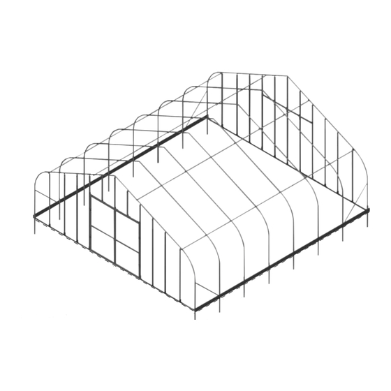
Gothic Pro Greenhouse — 30' Wide
Photo may show a different but similar model. Frame length may differ.
™
STK#
106310
106311
106312
106313
1
BEGIN HERE:
• Main Frame
• End Frame
• End Panels
DIMENSIONS
30' W x 12' 6" H x 36' L
30' W x 12' 6" H x 48' L
30' W x 12' 6" H x 72' L
30' W x 12' 6" H x 96' L
1
Advertisement
Table of Contents

Related Manuals for GrowSpan Gothic Pro 106310


Summary of Contents for GrowSpan Gothic Pro 106310
- Page 1 • End Frame • End Panels STK# DIMENSIONS 106310 30' W x 12' 6" H x 36' L ©2021 GrowSpan All Rights Reserved. Reproduction 106311 30' W x 12' 6" H x 48' L is prohibited without permission. 106312 30' W x 12' 6" H x 72' L 106313 30' W x 12' 6"...
-
Page 2: Table Of Contents
Important Information Contents READ THIS DOCUMENT BEFORE YOU BEGIN Thank you for purchasing this GrowSpan™ greenhouse. When properly Important Information ..................2 assembled and maintained, this product will provide years of reliable Customer-Supplied Materials ................. 5 service. These instructions include helpful hints and important information Parts ....................... - Page 3 Important Information LOCATION ASSEMBLY PROCEDURE Choosing the proper location is an important step before you begin. The Following the instructions as presented will help ensure proper assembly. following suggestions and precautions will help determine whether your Failing to follow these steps may result in an improperly assembled and selected location is the best location.
- Page 4 Important Information REQUIRED TOOLS ASSEMBLY NOTE: Install Tek screws using a clutched drill driver The following list identifies the main tools needed for assembly. Additional running approximately 750 RPM while applying approximately 50 lbs tools and supports may be needed depending on structure and location. of force.
-
Page 5: Customer-Supplied Materials
Customer-Supplied Materials RIBBON BOARDS AND BASEBOARDS FOR GREENHOUSES WITH DROP-DOWN OR ROLL-UP SIDE PANELS Greenhouses equipped with either the drop-down or roll-up side panel options require a combination of customer-supplied lumber for mounting. Review the information on this page and in Guides #2 & #3 for additional details. Recommended lumber dimensions are shown. All fasteners to attach the customer-supplied lumber to the greenhouse frame are included. -
Page 6: Parts
Parts The following graphics and photos identify different parts. (Some parts are not shown.) ASSEMBLY NOTE: Install Tek screws using a clutched drill driver running approximately 750 RPM while applying approximately 50 lbs of force. Do not use an impact driver to install Tek screws! FA4482B FAH009B &... -
Page 7: Install H-Channel - End Walls
Install H-Channel — End Walls The H-channel (113236Z096) design requires installation of the flat side facing out with channel side toward the frame. Some dia- grams and photos in this document may show installation of H-channel with channel side facing out. Design of the new H-channel does not allow channel-side out installation. -
Page 8: Anchoring & Frame Overview
Anchoring & Frame Overview ANCHOR ASSEMBLED FRAME ATTENTION: Position purlins evenly during frame assembly. Refer to Grid Consult the MUST READ document for anchoring information and suggestions. If needed, call customer diagram near the back of this guide service at 1-800-245-9881 for additional anchoring information. (Quick Start section) to position purlins, end clamps, and cross connectors. -
Page 9: Layout Building Site
Layout Building Site LAY OUT BUILDING SITE Gather parts: Prepare and set ground posts. Drive ground posts to the proper depth. Width of shelter is measured • Ground posts from center of one ground post to center of the remaining ground post. •... -
Page 10: Assemble Rafter - End Rafters (2)
Assemble Rafter — End Rafters (2) ASSEMBLE GREENHOUSE FRAME — END RAFTERS (2) Gather parts: After site is prepared and an inventory of parts is complete, continue with rafter assembly. • Rafter pipe (30G190SS403) • Rafter pipe (30G190SS401D) NOTE: All rafter assemblies consist of rafter tubes and purlin clamps. Consult rafter diagram below and in Quick Start section near the back of this guide before and during assembly. -
Page 11: Assemble Rafter - Interior
Assemble Rafter — Interior INTERIOR RAFTER ASSEMBLY Depending on length of building and available space, assemble all or some of the remaining rafters. Secure all rafter pipe splices as described on previous page. Set assembled rafters aside in an accessible location. Purlin cross-connector clamps for interior rafters are installed during frame assembly. 30G190SS403 (190S075) (190S075) -
Page 12: Assemble Frame
Assemble Frame BASIC FRAME ASSEMBLY TIPS Gather parts: • Enlist the services of experienced assistants. • All rafter assemblies and purlin pipe. • Never leave end rafter assembly standing without temporary supports (straps, braces, etc.). • Band clamps (QH1404) • Never remove end rafter temporary braces or straps without first connecting end rafter to at least two •... - Page 13 Assemble Frame FRAME ASSEMBLY — CONTINUED 2. Slide a band clamp (QH1404) onto each leg of first end rafter. Tape in place if needed. Set rafter on ground posts and secure to posts using 5/16" x 2 1/2" (FAG336B) bolts and nuts (FALB02B). Secure to top hole in ground post. Use rope, cable, strap, or braces to stabilize rafter. Rafter Band Clamp...
- Page 14 Assemble Frame FRAME ASSEMBLY — CONTINUED 4. Confirm on-center rafter spacing and connect first rafters using first run of purlin pipe (131S075). Position purlin according to frame diagrams found in Quick Start section of this guide. Use the 102547 cross connector for all interior rafters. Position plain end of pipe at end rafter. Do not allow purlin to extend beyond...
- Page 15 Assemble Frame FRAME ASSEMBLY — CONTINUED 7. Repeat steps to install first section of purlin pipe between end rafter and first interior rafter. Purlins run parallel with each other and are spaced as shown in diagrams. See Quick Start diagrams near back of this guide. Temporary bracing can be removed once all purlins are installed between first set of rafters. 8.
-
Page 16: Install Struts
Install Struts STRUT INSTALLATION — FRAME SIDES AT EACH END 4. Once strut is fully attached, drive an FA4482B Tek screw through each There are four (4) side struts for the frame. Struts are positioned between end band clamp into rafter pipe. Install in a location that will not contact roof rafters and first interior rafter. -
Page 17: Anchor Assembled Frame
Anchor Assembled Frame ANCHOR THE ASSEMBLED FRAME Additional purchase required for anchor components shown. At this point, anchor greenhouse frame. Consult the MUST READ document for anchoring information and suggestions. Call customer service at 1-800-245-9881 for additional anchoring information if needed. CAUTION: Anchor assembly is an integral part of the greenhouse construction. -
Page 18: End Wall Frame - Accessories Note
End Wall Frame — Accessories Note A NOTE ABOUT INSTALLING END WALL FRAMING FOR OPTIONAL HEATERS, VENT FANS, AND MOTORIZED SHUTTERS (if equipped): Optional accessories such as heaters, vent fans and motorized shutter units are typically installed in end walls of this greenhouse. Additional horizontal framing (included) is installed between vertical end wall frame tubes to mount these accessories. -
Page 19: Install End Wall Frame - General Notes
Install End Wall Frame — General Notes INSTALL END WALL FRAME Gather parts: Refer to end frame diagrams in Quick Start section and those on the following pages for • Square Tube 102897 assembly details. Read notes below to assemble end wall frame. •... - Page 20 Install End Wall Frame — General Notes INSTALL END WALL FRAME — CONTINUED View of end rafter from the outside. Header 92-1/4" Height of rough door opening QH1330 QH1330 QH1330 QH1330 96-3/4" Width Header End wall as seen from outside building.
- Page 21 Install End Wall Frame — General Notes INSTALL END WALL FRAME — CONTINUED Greenhouse end walls (front and back) are identical except as noted below and on end frame diagrams. If back wall includes optional door kit (additional purchase required), repeat end wall installation procedure and install framing for remaining end wall.
-
Page 22: Install End Wall Cladding
Install End Wall Cladding END PANEL INSTALLATION After end frames are assembled, install Seal open cells of panel tops polycarbonate panels. Steps that follow describe using foil tape. Flashing will EXCESS EXCESS one way to complete panel installation. cover panel top and sides once TRIMMED AND TRIMMED AND USED HERE... - Page 23 Install End Wall Cladding TYPICAL PANEL PREPARATION ATTENTION: Complete the following steps as directed after cutting panels to size. In some instances, this is before panel is attached to frame; in other instances, this is after panel is attached to frame. Procedure depends on panel location. 1.
- Page 24 Install End Wall Cladding Complete the following general steps to install end panels. 1. Consult panel location diagrams and select a panel. Begin at door opening edge and work toward outside edge of end wall. See X in diagram below for first panel. 2.
- Page 25 Install End Wall Cladding END PANEL INSTALLATION (continued) 6. Continue installing panels and aluminum profile in locations shown on end panel diagrams (Quick Start section) for front and back end walls. End wall with double door shown below. See next pages to install outer panels. Install aluminum H-channel between end panels.
- Page 26 Install End Wall Cladding ATTENTION: Follow the instructions on this page if your greenhouse includes polycarbonate roof panels. If your greenhouse includes a double-layer film roof, skip this page and continue with the next page. FOR GREENHOUSE WITH POLYCARBONATE ROOF PANELS ONLY To cut end panels A &...
- Page 27 Install End Wall Cladding ATTENTION: If your greenhouse includes polycarbonate roof panels, return to previous page to complete installation of end panels if you have not installed those. If your greenhouse includes a double-layer film roof, continue with steps on this page. FOR GREENHOUSE WITH DOUBLE-LAYER FILM ROOF ONLY To cut end panels A &...
-
Page 28: Shelter Care & Maintenance
If shelter is dismantled and moved, inspect all parts and connections before using. Do not reassemble using the same Tek screw mounting holes. Drive screws in new positions. • Depending on contents, construction of shelter, shelter materials, and shelter location, the potential for condensation exists. GrowSpan™ offers several items to alleviate a condensation condition. Please contact a GrowSpan™ representative for additional information. •... -
Page 29: Customer Notes
Customer Notes Revision date: 08.23.21 106310_11_12_13_Frame_End_Walls... -
Page 30: Quick Start Guide
Quick Start Guide QUICK START GUIDE 30' Wide Gothic Pro Greenhouse Finished Grade 106310_11_12_13_Frame_End_Walls Revision date: 08.23.21... -
Page 31: Front Profile
Front Profile 34G190SS403 Rafter Pipe End Rafter - 102857 Clamp End Rafter - 102857 Clamp Mid Rafter - 102547 Connector Mid Rafter - 102547 Connector End Rafter - 102857 Clamp End Rafter - 102857 Clamp 166P120 Rafter Chord Mid Rafter - 102547 Connector Mid Rafter - 102547 Connector Chord connected to Mid Rafters only using band clamps. -
Page 32: Connections
Connections 106310_11_12_13_Frame_End_Walls Revision date: 08.23.21... -
Page 33: Connection - Frame Details
Connection - Frame Details Revision date: 08.23.21 106310_11_12_13_Frame_End_Walls... -
Page 34: Side Profile - 106310
Side Profile - 106310 Customer- Supplied Baseboard Ground Level Ground Post 4'-0" Rafter Spacing 36'-0" Shelter Length 131S075 131S075 131S075 131S075 131S075 131P0735 ATTENTION: Buildings with drop-down side panels require a customer-supplied baseboard. For other applications and building options, baseboard is strongly recommended. -
Page 35: Side Profile - 106311
Side Profile - 106311 Customer- Supplied Baseboard Ground Ground Level Post ATTENTION: Buildings with drop-down side panels require a customer-supplied baseboard. For other applications and building options, baseboard is strongly recommended. Revision date: 08.23.21 106310_11_12_13_Frame_End_Walls... -
Page 36: Side Profile - 106312
Side Profile - 106312 Customer- Supplied Baseboard Ground Ground Level Post ATTENTION: Buildings with drop-down side panels require a customer-supplied baseboard. For other applications and building options, baseboard is strongly recommended. 106310_11_12_13_Frame_End_Walls Revision date: 08.23.21... -
Page 37: Side Profile - 106313
Side Profile - 106313 Customer-Supplied Ground 4'-0" Rafter Spacing 96'-0" Baseboard Level Ground Post Shelter Length (15) 131S075 131P0735 ATTENTION: Buildings with drop-down side panels require a customer-supplied baseboard. For other applications and building options, baseboard is strongly recommended. Revision date: 08.23.21 106310_11_12_13_Frame_End_Walls... -
Page 38: Front End Frame Diagram
Front End Frame Diagram 25 1/8" 48" C L - C L C L - C L VIEW 1 VIEW 2 92 1/4" INSIDE DIM 96 3/4" INSIDE DIM 48" 22 7/8" 98 1/4" 22 7/8" 48" C L - C L C L - C L C L - C L C L - C L... -
Page 39: Front End Frame Connection Details
Front End Frame Connection Details Revision date: 08.23.21 106310_11_12_13_Frame_End_Walls... -
Page 40: Back End Frame Diagram
Back End Frame Diagram 48" 22 7/8" 25 1/8" 47 15/16" 25 1/8" 22 7/8" 48" C L - C L C L - C L C L - C L C L - C L C L - C L C L - C L C L - C L NOTE: COLUMNS NOT DIMENIONED HAVE A NON-CRITICAL PLACEMENT... -
Page 41: End Wall: Panel Layout With Door
End Wall: Panel Layout with Door FILM ROOF ONLY: See page 27 to install POLYCARBONATE PANELS: end panels for film roof. Cut end panel to Use 104213 U-channel around follow rafter profile. See Guide #2. door panels and door opening. EXCESS EXCESS TRIMMED AND... -
Page 42: End Wall: Panel Layout Without Door
End Wall: Panel Layout without Door FILM ROOF ONLY: See page 27 to install end panels for film roof. Cut end panel to follow rafter profile. See Guide #2. EXCESS EXCESS TRIMMED AND TRIMMED AND USED HERE USED HERE POLYCARBONATE ROOF 4' X 8' 4' X 8' ONLY: See page 26 to... -
Page 43: H-Channel Installation Instructions
H-Channel Installation Instructions The new H-channel design requires installation of the flat side facing out with channel side toward building frame. Some diagrams and photos in this document show installation of original H-channel with channel side facing out. Design of new H-channel does not allow channel-side out installation. Use the diagrams on this page to install H-channel with flat side facing out.
Need help?
Do you have a question about the Gothic Pro 106310 and is the answer not in the manual?
Questions and answers