Condair DA Series Installation, Operation And Maintenance Manual
Desiccant dryer
Hide thumbs
Also See for DA Series:
- Installation and operation manual (128 pages) ,
- Installation, operation and maintenance manual (58 pages) ,
- Installation and operation manual (36 pages)

Related Manuals for Condair DA Series


Summary of Contents for Condair DA Series
- Page 1 IMPORTANT! Read and save these instructions. This manual to be left with the equipment. INSTALLATION, OPERATION, AND MAINTENANCE MANUAL Condair DA Series Desiccant Dryer Condair DA-Series Dehumidification...
- Page 2 Condair Ltd., except to the extent required for installation, operation or maintenance of customer's equipment. Liability Notice Condair Ltd. does not accept any liability due to incorrect installation , operation or operation of the equipment or due to the use of parts/components/equipment that are not authorized by Condair Ltd.
-
Page 3: Table Of Contents
Connecting the Wet Air Duct Outlet 6.5.9 Installing the Electrical Connections 6.5.9.1 Electrical Connections Checklist 6.5.10 Installation Work External Controls Connections 6.5.11 Connection of External Controls for Process Air EC Fan 6.5.12 Connection of External Controls for Regeneration Air EC Fan Condair DA 2597586_C_EN_2311_DA_IOM Contents... - Page 4 Shutting Down the Unit Configuring the Control Software Resetting Alarms Maintenance General Maintenance List Resetting the Service Reminder Troubleshooting 10.1 General Troubleshooting Condair DA Spare Parts List 11.1 Obtaining Spare Parts Commissioning 12.1 General 12.2 First-time Commissioning Decommissioning 13.1 General 13.2...
- Page 5 Important notes on maintenance 15.9.2 Maintenance list 15.9.3 Freeze Protection 15.9.3.1 Blowing-out coils 15.9.3.2 Flushing coils Appendix C: Additional instructions for the installation of Condair supplied transformers 16.1 Before you begin 16.2 Notes on the additional instructions 16.2.1 Limitation 16.2.2 General 16.2.3...
-
Page 6: Introduction
1.2.1 Limitations of the Manual The subject of this manual is the Condair DA Series Desiccant Dryer in its different versions. The vari- ous options and accessories that are described in this manual pertain to the proper operation of the equipment. -
Page 7: Storage Of Manual
Storage, Packaging, and Transportation Storage Store the Condair DA Series Desiccant Dryer in its original packaging inside a protected area that meets the following requirements until it is installed, or if it needs to be stored for an extended period of time: –... -
Page 8: Safety Precautions
Compliance Follow all local guidelines and regulations regarding the installation and operation of the unit; this includes (and not limited to) mounting, plumbing, water, gas, ventilation, and electrical connections. Please consult your local Condair representative to learn more. Introduction 2597586_C_EN_2311_DA_IOM... -
Page 9: For Your Safety
All personnel working with the Condair DA Series Desiccant Dryer unit must be familiar with, and comply with the appropriate regulations on workplace safety and prevention of accidents. - Page 10 The desiccant dryer must NEVER be used without the filters. This is to protect the rotor and heaters, and maintain capacity. The desiccant dryer must NOT be installed in areas where explosion proof equipment is required. For your Safety 2597586_C_EN_2311_DA_IOM Condair DA...
- Page 11 Preventing Unsafe Operation All personnel working with the Condair DA Series Desiccant Dryer must immediately report to the cus- tomer any alterations or changes to the unit that may affect safety, and secure the unit against accidental power-up. If it is suspected that the unit cannot be operated safely for any of the reasons listed below, shut it down immediately.
-
Page 12: Product Description
■ Controlling humidity in ■ Improving environment in equipment from corrosion museums and archives damp areas The Condair DA series comes in seven model sizes with two different voltages. Refer to "Technical for more information. Specification" on page 16 Product Description... -
Page 13: Model Designation
Fig. 1: Specification label Functional Description The Condair DA Series Desiccant Dryer operates with two air streams; a large volume air stream (pro- cess air) and a smaller volume air stream (reactivation air) that pass through a desiccant rotor in the unit. - Page 14 If available, the rotor guard can be turned on by going to the Service level page (refer to "Service Level Settings" on page 39). Product Description 2597586_C_EN_2311_DA_IOM Condair DA...
- Page 15 Electrical Panel The electrical panel is located behind the service panel, in a separate compartment in the dehumidifier. Switches and indications are located on a touch screen on the unit. Condair DA 2597586_C_EN_2311_DA_IOM Product Description...
-
Page 16: Product Specifications
Reactivation air fan speed: full speed or variable, depending on setting. Internal Control Humidity sensor – Setpoint entered at dehumidifier control interface. Humidity sensors are not included with the unit. The sensors are offered by Condair for purchase. Please contact your local Condair representative. Product Specifications 2597586_C_EN_2311_DA_IOM... -
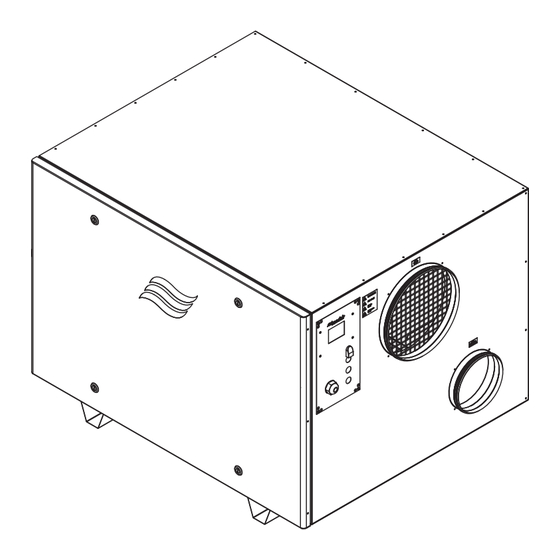
Page 17: Specification Drawings
Fig. 3: Specification Drawing Proc ess air inlet: Ø 15.7 in (400 mm) Dry air outlet: Ø 12.4 in (315 mm) Reactivation air inlet: Ø 7.9 in (200 mm) Wet air outlet: Ø 7.9 in (200 mm) Condair DA 2597586_C_EN_2311_DA_IOM Specification Drawings... -
Page 18: Installation And Planning
Observe and comply with all local and national codes dealing with electrical installations. Condair does not accept any liability for installation of humidification or dehumidification equipment by unqualified personnel, or the use of equipment and parts that are not authorized by Condair. Personnel Qualifications All installation work must be performed only by licensed personnel authorized by the customer. -
Page 19: Installation Overview
The installation requires a duct to remove wet air from the Condair DA Desiccant Dryer, an air duct for the reactivation air, a duct for the dry air outlet (recommended, especially for distribution), and connection to the mains supply (with disconnect switch). -
Page 20: Clearance Requirements
Prepare the Condair DA Series Desiccant Dryer for installation by ensuring the following site require- ments are satisfied. Report any discrepancies to your Condair representative. Ensure that the installation of the Condair DA Series Desiccant Dryer is compliant with all applicable local regulations and codes. -
Page 21: Installation
Installation The Condair DA Desiccant Dryer may be installed in the dehumidified room, or in a separate room. To obtain the best performance, equip diffuser to fan outlets. IMPORTANT! Ensure that the rooms supplying air to the dehumidifier and rooms requiring dry air from the dehumidifier are properly vented to reduce formation of pressure imbalance. - Page 22 Reactivation air connection Ø 7.9 in (200 mm), see "Connecting the Reactivation Air Duct Inlet" on page Wet air connection Ø 7.9 in (200 mm), see "Connecting the Wet Air Duct Outlet" on page Service panel Installation and Planning 2597586_C_EN_2311_DA_IOM Condair DA...
-
Page 23: Dampers And Air Balancing Schematic
>2° or have a condensate drain on its lowest point (p-trap with condensate well). If the unit is equipped with full modulating capacity, there is an increased risk of condensate. In this case, we recommend using corrosion resistant ducts. Condair DA 2597586_C_EN_2311_DA_IOM Installation and Planning... -
Page 24: Safety
Connecting the Process Air Duct Inlet Typical installations of the Condair DA Desiccant Dryer do not require a process air duct to the unit because the unit is installed in the space needing dehumidification. Instead, air into the dehumidifier is taken from the space directly. -
Page 25: Connecting The Reactivation Air Duct Inlet
6.5.8 Connecting the Wet Air Duct Outlet Wet air leaving the Condair DA Desiccant Dryer comes from the reactivation air that has passed through the internal heater and desiccant rotor. IMPORTANT! The reactivation air leaving the desiccant rotor is hot and can reach temperatures of over 176 °F (80 °C). -
Page 26: Installing The Electrical Connections
Power supply meet the voltage and current requirements shown on the specification label? Refer to "Model Designation" on page □ All cables fastened securely? □ All electrical connections meet applicable codes? □ Electrical installation meet the applicable national and local codes? Installation and Planning 2597586_C_EN_2311_DA_IOM Condair DA... -
Page 27: Installation Work External Controls Connections
Note: For modulating control do not connect any wires to terminal 1 & 2 of the dehumidifier. Note: This configuration package is offered by Condair (P/N 2597926). This package will require pro- gramming for dehumidification. Please contact your local Condair representative. - Page 28 "1" and "2" (On/Off Humidity Controller Input), "5" (GND) and "7" (+24V) of the control ter- minal block inside the control panel compartment. The connecting cable must be led through a cable gland into the control panel compartment. Note: This configuration package is offered by Condair (P/N 2597934). Please contact your local Condair representative. Connecting 0-10V humidistat with remote duct sensor...
-
Page 29: Connection Of External Controls For Process Air Ec Fan
"4", "5" and "GND" of the process air fan terminal block inside the control panel compartment. Important: Factory installed link "J5" between terminals "4" and "5" must be removed. The connecting cable must be led through a cable gland into the control panel compartment. Condair DA 2597586_C_EN_2311_DA_IOM Installation and Planning... -
Page 30: Connection Of External Controls For Regeneration Air Ec Fan
"10" (RA Fan Input), "12" (Constant Speed) and "5" (GND) of the control terminal block inside the control panel compartment. Important: Factory installed link "J6" between terminals "10" and "12" must be removed. The connecting cables must be led through cable glands into the control panel compartment. Installation and Planning 2597586_C_EN_2311_DA_IOM Condair DA... - Page 31 Factory installed link "J6" between terminals "10" and "12" must be removed and connected between terminal "11" and "10". The connecting cable must be led through the cable glands into the control panel compartment. Condair DA 2597586_C_EN_2311_DA_IOM Installation and Planning...
-
Page 32: User Interface
7.1 Control Software The programmable logic controller (PLC) in the Condair DA Desiccant Dryer features a touchscreen, LCD display, that allows you to control the dehumidifier, runtime meters, and alarms. The controller also features functions to protect the rotor from excess rotation, functions to safely cool the internal heater, and functions that control dehumidity through an external 0-10 V humidity sensor or control signal. -
Page 33: Main Page
0%. If a 0-10 V signal is used to control the humidity, the first heating stage occurs when the control signal exceeds 3 V. At 5 V, the second heating is activated (if applicable. The reactivation fan runs at full speed. Condair DA 2597586_C_EN_2311_DA_IOM User Interface... -
Page 34: I/O Input Outputs Page
See "Alarms" on page Service Level - (requires password) reset runtime meters. "Service Level Settings" on page Communication Setup - (requires password) communicate via Modbus, TCP/IP, or remotely. See "Communication Settings" on page User Interface 2597586_C_EN_2311_DA_IOM Condair DA... -
Page 35: Runtime
7.1.5.1 Runtime The Runtime page shows the active time of components in the Condair DA Desiccant Dryer, as well as the total dehumidifier runtime, and hours since maintenance. Here, you can find the runtime (in hours) for the: – Dehumidifier –... -
Page 36: Alarms
Reactivation air temperature thermostat – Process air fan thermal protection (stops the reactivation heaters when active) – Reactivation air fan thermal protection – Filter guard (when available) – High temperature limit (when available) – OH2 Overheat protection User Interface 2597586_C_EN_2311_DA_IOM Condair DA... - Page 37 ) next to an alarm brings you to the Alarm Details page, where you press Ack to acknowledge the alarm. Pressing Reset will reset the alarm, only if the cause for the alarm is NOT active. IMPORTANT! Reset an alarm after it has been acknowledged. Condair DA 2597586_C_EN_2311_DA_IOM User Interface...
- Page 38 Use the left and right arrows on the touchscreen to go between alarm entries. To clear the alarm history, go to the second service level page (see "Service Level Settings" on page 39, requires password) and press Clear alarm history. User Interface 2597586_C_EN_2311_DA_IOM Condair DA...
-
Page 39: Service Level Settings
PID output - displays the dehumidication demand between 0-100 (stop = 0, start = 30). IMPORTANT! The PID settings should not be changed. Consult your Condair representative. In addition to this, the second service level page shows buttons that will allow you to clear the alarm history (refer to "Reset Alarms"... -
Page 40: Communication Settings
Note: The Modbus data points are located here:"Appendix A-4: Communication" on page Modbus Network ID Default: 35 RS 485 Choose between six different combinations, then save. Modbus TCP/IP Enter the IP Address, Gateway, and Subnet, then save. User Interface 2597586_C_EN_2311_DA_IOM Condair DA... -
Page 41: Operation
Operation General Personnel Qualifications The Condair DA Series Desiccant Dryer must only be operated by personnel who are adequately qualified, competent, and are authorized by the customer. Safety Observe the following safety precautions. DANGER! Risk of electric shock! The unit is mains powered. Using the On/Off button on the touch screen to shut down the unit will not remove power from the unit. Live parts may be exposed when the access panels or doors are removed. Touching live parts may cause severe injury or even death. -
Page 42: Starting Up
The desiccant dryer must NOT be installed in areas where explosion proof equipment is required. Starting Up Ensure that the proper commissioning has been performed, and the Condair DA Desiccant Dryer is connected to the mains power supply. Refer to "First-time Commissioning" on page To start the Condair DA Desiccant Dryer: 1. -
Page 43: Shutting Down The Unit
Shutting Down the Unit IMPORTANT! The Condair DA is mains powered. Disconnect the dehumidifier from the mains power supply before opening any service panels. Ensure that the external disconnect switch has removed the unit from the mains power supply. To shut down the Condair DA Desiccant Dryer: 1. -
Page 44: Maintenance
Direct the compressed air in the opposite direction of process air flow to prevent particles from embedding further into the desiccant rotor. For severe levels of debris and dust, consult your Condair representative, then (optional) use water to wash the rotor. The rotor bearings and rotor surface should also be inspected for any damages. -
Page 45: Resetting The Service Reminder
The dehumidifier alerts you when a filter or seal need to be changed, or when the interval runtime hours for the fans and motor exceed a factory defined threshold. The threshold values for runtime hours may be changed, but only after consulting your Condair representative. For more information about runtime hours, refer to "Service Level Settings"... -
Page 46: Troubleshooting
Condair service technicians. Troubleshooting the Condair DA Series Desiccant Dryer may require the user to access the inside of the unit, to the control cabinets, which may expose the user and equipment to hazards described in "For... - Page 47 Contactor seizing. Check the reactivation heater, and check the volume of airflow entering the reactivation side. There is a delay between the heater stages to ensure there is no high current inrush that occurs during startup. Condair DA 2597586_C_EN_2311_DA_IOM Troubleshooting...
- Page 48 This reduction in airflow can be accomplished by adjusting the damper or using a control signal/ potentiometer. It’s essential to ensure that the airflow is not reduced significantly, as this can result in reduced performance or even damage to the unit. Troubleshooting 2597586_C_EN_2311_DA_IOM Condair DA...
-
Page 49: Condair Da Spare Parts List
Condair DA Spare Parts List Fig. 8: Spare Parts (Refer to "Condair DA 300N-800N Parts List" on page 51 "Condair DA 1400N - 2400N Parts List" on page Condair DA 2597586_C_EN_2311_DA_IOM Condair DA Spare Parts List... - Page 50 113 105 110 111 Fig. 9: Spare Parts (Refer to "Condair DA 300N-800N Parts List" on page 51 "Condair DA 1400N - 2400N Parts List" on page Condair DA Spare Parts List 2597586_C_EN_2311_DA_IOM Condair DA...
- Page 51 Table 3: Condair DA 300N-800N Parts List Condair DA Model 300N 400N 600N 800N Item Item Part Description Number Auxiliary Switch, MCB DIN Rail 2594702 Breaker MCB, DIN rail, 4 Amps 2594703 Breaker MCB, DIN rail, 13 Amps 2594704 Breaker MCB, DIN rail, 15 Amps...
- Page 52 SP Heater Bank, DA 400, 500V 2604796 (Replaces PN: 2601271) SP Heater Bank, DA 300, 500V 2604795 (Replaces PN: 2601270) SP Heater Bank, DA 300-400, 208V 2601265 N/S = item not shown Condair DA Spare Parts List 2597586_C_EN_2311_DA_IOM Condair DA...
- Page 53 Table 4: Condair DA 1400N - 2400N Parts List Condair DA Model 1400N 2000N 2400N Item Item Part Description Number Auxiliary Switch, MCB DIN Rail 2594702 Breaker MCB, DIN rail, 4 Amps 2594703 Breaker MCB, DIN rail, 13 Amps 2594704...
-
Page 54: Obtaining Spare Parts
2604798 (Replaces PN: 2601282) SP Heater Bank, DA 1400-2000, 208V 2601269 N/S = item not shown 11.1 Obtaining Spare Parts Obtain additional spare parts from your local Condair Agent, or through www.CondairParts.com. Condair DA Spare Parts List 2597586_C_EN_2311_DA_IOM Condair DA... -
Page 55: Commissioning
12.2 First-time Commissioning The unit must always be commissioned for the first time by a service technician from your Condair re- presentative, or by personnel who are well trained and authorized by the customer. For this reason, this manual only provides an outline, and not the details of the commissioning protocol. - Page 56 Check to confirm that the air entering the unit is not contaminated or polluted. • Inspect the area underneath the rotor for any powder duct. If any is a present, please use a brush to remove it from the inside of the unit. Commissioning 2597586_C_EN_2311_DA_IOM Condair DA...
-
Page 57: Decommissioning
Decommissioning 13.1 General If the Condair DA Series Desiccant Dryer needs to be replaced or removed from service for disposal, strictly follow the instructions in this section. Personnel Qualifications All decommissioning work must be performed only by a qualified service technician authorized by the customer. -
Page 58: Appendix A-1: Installation Checklist
Power supply meet the voltage and current requirements shown on the specification label? Refer to "Model Designation" on page □ All cables fastened securely? □ All electrical connections meet applicable codes? □ Electrical installation meet the applicable national and local codes? Appendix A 2597586_C_EN_2311_DA_IOM Condair DA... -
Page 59: Appendix A-2: Maintenance Checklist
"Maintenance Procedures" for descriptions on mainte- nance procedures. Table 5: Maintenance Log Component Frequency Dates Last Performed (DD/MM/YY) and Initials Filters Monthly or as needed Rotor (and Annually - contact Condair bearings) representative Rotor Drive Bi-annually Belt Rotor Seals Bi-annually Heater Bi-annually - visually ins- pect the heater. -
Page 60: Appendix A-3: Wiring Diagrams
14.3 Appendix A-3: Wiring Diagrams s s s s s s s s s Abb. 1: Wiring Diagram for DA Series Dehumidifiers 208V Refer to the wiring diagram on the actual unit Appendix A 2597586_C_EN_2311_DA_IOM Condair DA... - Page 61 Abb. 2: Wiring Diagram DA Series Dehumidifiers 480V (S2) - Refer to the wiring diagram on the actual unit Condair DA 2597586_C_EN_2311_DA_IOM Appendix A...
- Page 62 PTC Heater PTC Heater PTC Heater PTC Heater PTC Heater PTC Heater PTC Heater PTC Heater DA 500VAC HEATER BANK,(S2) Wiring Diagram 2604480 Revision: B Date: 02/21/2023 Fig. 10: DA 500VAC (S2) Heater Bank Wiring Diagram Appendix A 2597586_C_EN_2311_DA_IOM Condair DA...
- Page 63 F-2 Heater PTC Heater PTC Heater F-3 Heater PTC Heater PTC Heater F-4 Heater PTC Heater DA 208VAC HEATER BANK Wiring Diagram 2597584 Revision: B Date: 02/21/2023 Fig. 11: DA 208VAC Heater Bank Wiring Diagram Condair DA 2597586_C_EN_2311_DA_IOM Appendix A...
-
Page 64: Appendix A-4: Communication
Appendix A-4: Communication 14.4.1 Modbus The Condair DA Desiccant Dryer can be ordered with optional Modbus TCP/IP or Modbus RS485 net- work cards installed in the unit's PLC. Connections can be made with an Ethernet (RJ45) or RJ11 cable. Note: The Condair DA Desiccant Dryer supports Modbus RTU with RS 232 interfaces. -
Page 65: Tcp/Ip Network Settings
Enter "ping" and the IP address you created in step 5. Ex. > ping 192.168.0.150 d. If there are lost packets, there is no connection. Check the Ethernet connection and IP address and try again. Condair DA 2597586_C_EN_2311_DA_IOM Appendix A... -
Page 66: Modbus Datapoints
React. Heater step 1 16385 1=On Process air fan 16386 1=On React. Air fan 16387 1=On Drive motor 16388 1=On Alarm indication 16389 1=On React. Heater step 2 16390 1=On React. air fan 10V control relay Appendix A 2597586_C_EN_2311_DA_IOM Condair DA... -
Page 67: Bacnet
14.4.4 BACnet The Condair DA Desiccant Dryer can be ordered with optional FieldServer gateway card factory installed to translate DA Desiccant Dryers Modbus TCP (fixed IP) into four optional protocols with configurable IP, node and other settings. 14.4.4.1 Network Settings When factory installed, CAT 5 Ethernet cable is connected from the PLC to gateway at ETH1 port. Con-... -
Page 68: Configure The Gateway
Click System Restart • Select/Adjust Desired Parameters • Select/Adjust Desired Parameters • Click Submit • Click Submit • Click System Restart • Click System Restart • Add DA Device - Under Active Profiles – Click <Add>. Appendix B 2597586_C_EN_2311_DA_IOM Condair DA... -
Page 69: Changing Ip Addresses/ Troubleshooting
Example after entering values (example is for BACnet IP) • The gateway configuration is complete. 14.4.4.3 Changing IP Addresses/ Troubleshooting • Connect computer and login to gateway as described in point 6 above. • Click Diagnostics & Debugging • Click Setup > Network Settings Condair DA 2597586_C_EN_2311_DA_IOM Appendix B... - Page 70 Set ETH1 IP address to connect to PLC or set ETH2 IP address to connect to the laptop (BMS). • Default routing priority is set to ETH2 and should not be changed. In case of communication issues check that this is set correctly. Appendix B 2597586_C_EN_2311_DA_IOM Condair DA...
- Page 71 BINARY INPUT 14 React Air Fan 1=On BINARY INPUT 15 Driver Motor 1=On BINARY INPUT 16 Alarm Indication 1=On BINARY INPUT 17 React Heater Step 2 1=On BINARY INPUT 18 React Air Fan 10V Control 1=On Relay Condair DA 2597586_C_EN_2311_DA_IOM Appendix B...
-
Page 72: Appendix B: Additional Instructions Pre- And Post-Cooling Modules
Please observe and comply with all information and safety instructions contained in this sections, as well as all relevant documentation of components of the installed dehumidification system. If you have additional questions, please contact your Condair representative. They will be glad to assist you. 15.2 Notes on the additional instructions 15.2.1 Limitation... -
Page 73: Receiving And Storage
The standard delivery includes the cooling modules as ordered packed in cardboard boxes. Please note that Condair does not supply as part of the delivery of the cooling module, the cooling coil valves, temperature sensor, and controller required to operate the coil. Please contact your Condair representative for the size of valve that will be required for your specific site operation. -
Page 74: Product Overview
All Condair coils are sized for operation with chilled water at a supply temperature of 43 °F (6 °C) and a return temperature of 53 °F (13 °C). If your site’s chilled water system has different supply and return temperatures, please contact Condair before installation to verify and certify the performance of the cooling module. - Page 75 Process Air Flow Process Air Outlet Process Air Inlet Post Cooling Condair DA ***N Dehumidifier Coil Connections Cooling Rear Side Elevation Coil Connections Fig. 13: Installation layout of the cooling modules with the DA desiccant dryer Condair DA 2597586_C_EN_2311_DA_IOM Appendix B...
-
Page 76: Product Specifications
(2) 1-1/2" MPT STEEL CONNECTIONS RETURN FLOW (1) 3/8" MPT SUPPLY STEEL DRAIN HEADER END RETURN END Fig. 14: Pre-cooling module drawing Table 10: Condair DA Series pre-cooling modules Pre-cooling modules Max. cooling Height Length Length Depth Dept Dept MPT/ Actual OD... -
Page 77: Post-Cooling Module
(2) 1-1/2" MPT STEEL CONNECTIONS RETURN FLOW (1) 3/8" MPT SUPPLY STEEL DRAIN HEADER END RETURN END Fig. 15: Post-cooling module drawing Table 11: Condair DA Series post-cooling modules Post-cool modules Max cooling Height Length Length Depth Dept ( Dept MPT/ Actual OD... -
Page 78: Installation
Supply Fig. 16: Cooling module connection locations If you are unsure about any portion of the installation, contact your Condair representative for assistance. 1. Carefully remove the coil from the shipping package to avoid damage to the finned surface area. - Page 79 CAUTION! Failure to properly install the coil can result in irreparable damage to the cooling module as well as other components in the system. Condair DA 2597586_C_EN_2311_DA_IOM Appendix B...
- Page 80 Client Supply Condair Supply Air vent t u r n Vent Gate valve A i r fl o w Drain Dirt Leg Union Fig. 18: Horizontal airflow piping diagram Appendix B 2597586_C_EN_2311_DA_IOM Condair DA...
-
Page 81: Commissioning
Pressure losses greater than 5 PSIG would indicate a larger leak that should be isolated and repaired. If the coil itself is found to be leaking, contact, contact your Condair representative. Note: All field brazing and welding should be performed using high-quality materials and an inert gas purge (like nitrogen) to reduce oxidation of the internal surface of the coil. -
Page 82: Maintenance
5. If automatic air vents are not utilized, periodic venting of the coil is required for removing the air ac- cumulated in the tubes and maintaining proper coil performance. DANGER! Caution should be exercised to avoid injury. High pressure and/or high temperature fluids can cause serious personal injury. Appendix B 2597586_C_EN_2311_DA_IOM Condair DA... -
Page 83: Freeze Protection
6. Let the coil stand for several minutes, then blow it out again. If water comes out, repeat the blowing operation. 7. Leave all plugs out and drains open until the threat of freezing has passed. Condair DA 2597586_C_EN_2311_DA_IOM Appendix B... -
Page 84: Flushing Coils
15.9.3.2 Flushing coils Condair recommends the use of inhibited glycol designed for HVAC applications for corrosion protec- tion. The recovered fluid can then be used to flush other coils. Select an inhibited glycol solution that will protect the coil from the lowest temperatures that may occur at the coil locality. The following table is provided only as a guide on the freezing point of glycol solutions according to their concentration in glycol. - Page 85 Vent A i r fl o w Shut-off Valve with hose connection Throttling Valve Vent Hole Drain Shut-off Valve with hose connection Pump Inhibited Glycol Reservoir Fig. 19: Coil flushing system diagram Condair DA 2597586_C_EN_2311_DA_IOM Appendix B...
-
Page 86: Appendix C: Additional Instructions For The Installation Of Condair Supplied Transformers
Any other type of application, without the written consent of Condair, is considered as not conforming with the intended purpose and may lead to hazardous operation of the transformer and will void any warranty. -
Page 87: Receiving, Storage And Ventilation
The standard delivery includes the transformer shipped on pallets which are to be removed at in- stallation. Please note that Condair does not supply as part of the delivery of the transformer the connecting cables between transformer primary/secondary windings and electrical connector lugs. -
Page 88: Product Overview
A step-down transformer is designed to convert high-voltage electrical power from a 600V source to lower 480V output to use our DA Series desiccant dehumidifier. It is designed to achieve this transformation through primary and secondary windings around an iron core. -
Page 89: Technical Specification
345 lb 380 lb Conduit Entry Side knock-out standards Side knock-out standards Side knock-out standards on all units; on all units; on all units; Warranty 10 years. 10 years. 10 years. Table 14: Transformer technical specification Condair DA 2597586_C_EN_2311_DA_IOM Appendix B... -
Page 90: Ampacity Rating For Transformer Wiring
For a three phase transformer: Use wires with an ampacity rating sufficient for the current values below. Volt Amperes Line Amperes = 1.732 x Line Volts Current in Amperes 480V 600V 14.4 36.1 28.9 54.1 43.1 Fig. 20: Ampacity Rating for Transformer Wiring Appendix B 2597586_C_EN_2311_DA_IOM Condair DA... -
Page 91: Installation
5. The breaker circuit on the output of the transformer can be connected to the dehumidifier. 6. Energize the unit and check the secondary voltage to ensure proper load is being supplied to the dehumidifier. Condair DA 2597586_C_EN_2311_DA_IOM Appendix B... -
Page 92: Sample Installation
600 V 480 V Dry Air Out Process Air In Desiccant dryer DA Series Transformer 600V/480V Regeneration Air In Fig. 21: Install transformer in the electrical room and DA Series Dehumidifier in the space to dehumidify. Appendix B 2597586_C_EN_2311_DA_IOM Condair DA... - Page 93 Transformer 600V/480V Fig. 22: Install both the DA Series Dehumidifier and Transformer in Mechanical Room Note: Damper are not illustrated in the sketch above, however dampers are recommended when com- missioning the unit for achieving the design airflow. Please refer to the IOM for additional information.
- Page 94 Notes...
- Page 95 Warranty Condair Inc. and/or Condair Ltd. (hereinafter collectively referred to as THE COMPANY), warrant for a period of two years after installation or 30 months from manufacturer’s ship date, whichever date is earlier, that THE COMPANY’s manufactured and assembled products, not otherwise expressly warranted, are free from defects in material and workmanship.
- Page 96 CONSULTING, SALES AND SERVICE: CANADA 2740 Fenton Road Ottawa, ON, K1T 3T7 Tel: 1.866.667.8321 Fax: 613.822.7964 na.info@condair.com www.condair.com...
Need help?
Do you have a question about the DA Series and is the answer not in the manual?
Questions and answers