Table of Contents
Advertisement
Advertisement
Table of Contents

Subscribe to Our Youtube Channel
Related Manuals for OBD2 MS310


Summary of Contents for OBD2 MS310
- Page 1 MS310 USER’S MANUAL CAR PROFESSIONAL SCAN TOOL...
-
Page 2: Table Of Contents
Table of Contents Precautions ................1 Using the Car Professional Scan Tool ........2 2.1 Tool Description .............. 2 2.2 Specifications ..............3 2.3 Accessories Included ............3 2.4 Navigation Characters ............. 3 2.5 Vehicle Power ..............3 2.6 System Setup ..............4 2.7 Vehicle Coverage ............ -
Page 3: Precautions
1. Precautions To avoid personal injury or damage to the vehicles, read this instruction manual and observe the following safety precautions whenever working on a vehicle: • Be sure to test your vehicle in a safe environment. • Wear ANSI-compliant eye protection tools. •... -
Page 4: Using The Car Professional Scan Tool
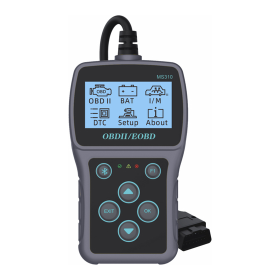
2. Using the Car Professional Scan Tool 2.1 Tool Description ① OBD II CONNECTOR - Connects the Car Professional Scan Tool to the vehicle’s Data Link Connector (DLC). ② LCD DISPLAY - Indicates test results. ③ UP button - Roll up the menu and submenu in menu screen. -
Page 5: Specifications
2.3 Accessories Included QR code On the back of the product for User’s Manual download - Instructions on tool operations OBD2 cable -- Provides power to tool and communicates between tool and vehicle. 2.4 Navigation Characters Characters used to help navigate the Car Professional Scan Tool are: “”... -
Page 6: System Setup
• A plastic DLC cover may be found for some vehicles and you need to remove it before plugging the OBD2 cable. Plug OBD II cable to the vehicle’s DLC. 2.6 System Setup The Car Professional Scan Tool allows you to make the following adjustments and settings: Language: Selects desired language. - Page 7 • The number "x/x" to the upper right comer of the screen indicates total number of items under the menu and sequence of currently selected item. Language • English is the default language. From System Setup menu, use UP/DOWN button to select Language, and press OK button.
- Page 8 Use UP/DOWN button to select the desired language and press OK button to save your selection and return to previous menu. Unit Of Measurement • Metric is the default measurement unit. From System Setup menu, use UP/DOWN button to select Unit of Measure and press OK button. From Unit of Measure menu, use UP/DOWN button to select the desired unit of measurement.
- Page 9 Press OK button to save your settings and return to previous menu. Contrast From System Setup menu, use UP/DOWN button to select Contrast and press OK button. From Contrast menu, use UP/DOWN button to adjust contrast.
- Page 10 Press OK button to save your settings and return to previous menu. Backlight From System Setup menu, use UP/DOWN button to select Backlight, and press OK button. From Backlight menu, use UP/DOWN button to adjust backlight. Press OK button to save your settings and return to previous menu.
- Page 11 Key Beep From System Setup menu, use UP/DOWN button to select Key Beep, and press OK button. From Key Beep menu, use UP/DOWN button to select OFF or ON. Press OK button to save your settings and return to previous menu. F1 Key Function From System Setup menu, use UP/DOWN button to select F1 Key Function, and press OK button.
- Page 12 From F1 Key Function menu, use UP/DOWN button to select F1 key function. Press OK button to save your settings and return to previous menu. Exiting System Setup 1) Press EXIT button to return to Main Screen.
-
Page 13: Vehicle Coverage
2.7 Vehicle Coverage This OBDII / EOBD Car Professional Scan Tool is specially designed to work with all OBD II compliant vehicles, including those equipped with the next-generation protocol - Control Area Network (CAN). It is required by EPA that all 1996 and newer vehicles (cars and light trucks) sold in the United States must be OBD II compliant and this includes all Domestic, Asian and European vehicles. -
Page 14: Obd Ii Diagnostics
Check if the Car Professional Scan Tool OBD II connector is securely connected to the vehicle’s DLC; Verify that the vehicle is OBD2 compliant; Turn the ignition off and wait for about 10 seconds. Turn the ignition back to on and repeat the procedure from step If the “LINKING ERROR"... -
Page 15: Reading Codes
After the system status is displayed (MIL status, DTC counts, Monitor status), wait a few seconds or press any key for Diagnostic Menu to come up. 3.1 Reading Codes 1) Use UP/DOWN button to select Read Codes from Diagnostic Menu and press OK button From Trouble Codes menu, use UP/DOWN button to select the type of trouble codes, press OK button. - Page 16 • If there is a Stored trouble code, the red LED will light up. • If there is a Pending trouble code, the yellow LED will light up. View DTCs and their definitions on screen. • The control module number, sequence of the DTCs, total number of codes detected and type of codes (Generic or Manufacturer specific, Stored or Pending codes) will be observed on the upper right hand comer of the display.
-
Page 17: Erasing Codes
3.2 Erasing Codes CAUTION: Erasing the Diagnostic Trouble Codes may allow the Car Professional Scan Tool to delete not only the codes from the vehicle’s on-board computer, but also “Freeze Frame” data and manufacturer enhanced data. Further, the I/M Readiness Monitor Status far all vehicle monitors is reset to Not Ready or Not Complete status. -
Page 18: Viewing Freeze Frame Data
3) If you want to proceed with erasing the codes, press OK button to erase. • If the codes are cleared successfully, an “Erase Done!”message shows up. • If the codes are not cleared, then an “Erase Failure. Turn Key on with Engine off!”message displays. 4) Wait a few seconds or press any key to return to Diagnostic Menu. -
Page 19: Retrieving I/M Readiness Status
If the retrieved information covers more than one screen, use UP/DOWN button, as necessary, until all data have been shown up. • The number “x/x” to the upper right comer of the screen indicates total number of screens the retrieved freeze frame covers and sequence of currently displayed data. - Page 20 for compliance to a state emissions program. Some latest vehicle models may support two types of I/M Readiness tests: Since DTCs Cleared -indicates status of the monitors since the DTCs are erased. This Drive Cycle- indicates status of monitors since the beginning of the current drive cycle.
- Page 21 3) Use UP/DOWN button to view the status of the MIL light (“ON” or “OFF”) and the following monitors: • Misfire monitor-- Misfire monitor • Fuel System Mon.-- Fuel System Monitor • Comp. Component-- Comprehensive Components Monitor • Catalyst Mon.-- Catalyst Monitor •...
-
Page 22: Viewing Vehicle Information
4) If the vehicle supports readiness test of “This Drive Cycle”, a screen of the following will be displayed: The number “x/x” to the upper right comer of the screen indicates total number of screens the retrieved data cover and sequence of currently displayed data. - Page 23 2) Wait a few seconds or press OK button to continue. • If the vehicle does not support this mode, a “The selected mode is not supported!”message shows on the display. From Vehicle Info. menu, use UP/DOWN button to select an available item to view and press OK button.
-
Page 24: Live Pcm Data
4) View retrieved vehicle information on the screen. 5) Press EXIT button to return to previous menu. 3.6 Live PCM Data The Live PCM Data function can retrieve vehicle realtime data of Mode 1. Use UP/DOWN button to select Live PCM Data from Diagnostic Menu and press OK button Use UP/DOWN button to change page in Live PCM Data interface. -
Page 25: Realtime Curve
Press EXIT button to return to the previous menu. 3.7 Realtime Curve The Realtime Curve function can retrieve vehicle realtime data of Mode 1 and displays it in a curved fashion. Use UP/DOWN button to select Realtime Curve from Diagnostic Menu and press OK button Use UP/DOWN button to select the item that need to be displayed. -
Page 26: O2 Sensor Test
In the realtime curve screen, Use UP/DOWN button to change the update speed of the curve. Press EXIT button to return to the previous menu. 3.8 O2 Sensor Test The O2S Monitor Test function allows retrieval and viewing of O2 sensor monitor test results for the most recently performed tests from the vehicle’s on-board computer. -
Page 27: On-Board Mon. Test
Use UP/DOWN button to select test result and press OK button to view additional data. Press EXIT button to return to the previous menu. 3.9 On-Board Mon. Test The On-Board Mon. Test function retrieves and displays test results for emission-related power train components and systems that are not continuously monitored. - Page 28 Wait until the scan tool validates the PID MAP. Use UP/DOWN button to select the monitor to view and press OK button. Use UP/DOWN button to select test result and press OK button to view additional data.
-
Page 29: Component Test
Press EXIT button to return to the previous menu. 3.10 Component Test The Component Test initiates a leak test for the vehicle’s EVAP system. The scan tool itself does not perform the leak test, but commands the vehicle’s on-board computer to start the test. Different vehicle manufacturers might use different criteria and methods for stopping the test once it has been started. -
Page 30: Exiting Obdii Test
Wait for the scan tool to display the Component Test menu. Press OK button to send command. Wait a few seconds or press any key to return to previous screen. 3.11 Exiting OBDII Test To exit OBDII test, press EXIT button in Diagnostic Menu. A warning message comes up asking your confirmation. -
Page 31: Battery Test
• If you do not want to exit, use UP/DOWN button to select NO and press OK button to return. 3.12 Battery Test The Battery Test function can measure the battery voltage, view the battery voltage curve and test the battery life. To enter the Battery Test menu Use UP/DOWN button to select Battery Test from Main Screen and press OK button. - Page 32 Battery monitoring From Battery Test menu, use UP/DOWN button to select Battery monitoring, and press OK button. Press EXIT button to return to the previous menu. Battery life From Battery Test menu, use UP/DOWN button to select Battery Life, and press OK button.
- Page 33 There will be some prompts for the steps on the screen, in order to get accurate test results, please be sure to follow the prompts. Follow the tips above,Turn off the engine, wait a moment and turn it on again. The results of battery life are displayed on the screen by arrow viewing.
-
Page 34: Dtc Lookup
3.13 DTC Lookup 3.13 DTC Lookup The DTC Lookup function is used to search for definitions of The DTC Lookup function is used to search for definitions of DTCs stored in the DTC library and for DTC Guide information. DTCs stored in the DTC library and for DTC Guide information. Use UP/DOWN button to select DTC Lookup from Main Use UP/DOWN button to select DTC Lookup from Main Screen and press OK button. -
Page 35: Bluetooth Mode
3.14 Bluetooth Mode Under any menu, press the Bluetooth button and it will enter Bluetooth mode Scan the QR code on the right side of the screen with your phone to download and install the YMOBD® software. 2) Open the software, Bluetooth will automatically scan and connect. -
Page 36: Warranty And Service
4. Warranty and Service 4.1 Limited One Year Warranty This product will be free from all defects in materials and workmanship for a period of one (1) year from the date of the original purchase, subject to the following terms and conditions: The sole responsibility of us under the Warranty is limited to either the repair or, at the option of us, replacement of...
Need help?
Do you have a question about the MS310 and is the answer not in the manual?
Questions and answers