Table of Contents
Advertisement
Quick Links
HRX-aQ Range
Mechanical Ventilation with Heat Recovery
Product Code: AQH200-B
Installation Instructions
1.0 SAFETY INFORMATION
DO NOT SWITCH OFF THE UNIT – it is designed to run continuously. If the unit is switched
•
off, indoor pollutants and moisture levels may increase which could endanger your health or
damage your home. It is important to follow the advice in this manual and correctly maintain the
system to ensure a healthy indoor environment.
All wiring must be in accordance with prevailing national regulations, for example the current
•
IEE Wiring Regulations BS7671. The electrical installation should be inspected and tested by a
suitably qualified person after completion.
The installer is responsible for the installation and electrical connection of this system on site.
•
It is the responsibility of the installer to ensure that the equipment is safely and securely installed
and left only when electrically and mechanically safe.
When installing the appliance, care should be taken not to damage any hidden utilities.
•
Ensure that the mains supply (Voltage and Frequency) complies with the rating label.
•
Isolate from power supply before removing any covers. During installation / maintenance
•
ensure all covers are fitted before switching on the mains supply.
The appliance should be provided with a local double pole fused spur fitted with a 3 Amp fuse
•
and a minimum contact separation of at least 3mm.
This unit must be earthed.
•
Ducting must be securely fixed with screws to the spigot to prevent access to live parts. Duct
•
runs terminating close to the fan must be adequately protected by suitable guards.
All regulations and requirements must be strictly followed to prevent hazards to life and
•
property, both during and after installation and any subsequent servicing or maintenance.
This appliance should not be used by children or persons with reduced physical, sensory or
•
mental capabilities or lack of experience and knowledge, unless they have been given supervision
or instruction concerning the safe use of the appliance by a person responsible for their safety.
Children shall not play with the appliance. Cleaning and user maintenance shall not be carried
out by children.
LAB1199R | OCTOBER 2023
PAGE 1
Advertisement
Table of Contents

Related Manuals for Domus HRX-aQ AQH200-B


Summary of Contents for Domus HRX-aQ AQH200-B
- Page 1 HRX-aQ Range Mechanical Ventilation with Heat Recovery Product Code: AQH200-B Installation Instructions 1.0 SAFETY INFORMATION DO NOT SWITCH OFF THE UNIT – it is designed to run continuously. If the unit is switched • off, indoor pollutants and moisture levels may increase which could endanger your health or damage your home.
- Page 2 A condensate drain should be installed from the appliance to an appropriate drain location. • DOMUS Ventilation recommends the 297 condensate drain kit. The condensate drain and associated pipe work must be cleared of debris prior to • commissioning and insulated where it passes through unheated spaces and voids.
-
Page 3: General Description
A manual boost switch is provided to increase the ventilation rate, e.g. when cooking or showering thereby maintaining a comfortable indoor 2.1 Pack Includes environment. • Domus HRX-aQ appliance A programmable user interface is provided to thereby maintaining a • Ventilation user-control centre comfortable indoor environment and includes the following features: •... -
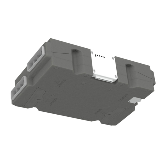
Page 4: Installation
2.2 Physical Specification The HRX ceiling appliance must be connected to the duct work as shown below; duct connections can not be substituted. When viewed from below, the filter access and duct configuration is as shown on the diagram below: Filter access Unit Dimensions net weight 7.9kg... - Page 5 The fresh supply air must be drawn in from the exterior of the property. If drawn through a wall, a Domus Ventilation 905 airbrick should be fitted. If drawn in through a pitched roof a Domus Ventilation 4411/4411T universal roof terminal should be fitted or a proprietary roof terminal designed for mechanical ventilation with a free area of at least 10,000mm².
- Page 6 5.0 WIRING 5.1 Wiring Centre PCB Layout and Connections BLUE YELLOW GREEN Unit Wiring LAB1199R | OCTOBER 2023 PAGE 6...
-
Page 7: User Interface
6.0 COMMISSIONING IMPORTANT: Ensure that the protective covers have been removed from the filters. When the wiring connections have been checked, switch on the mains supply and check that the system is operating correctly (Section 7.0). Airflow rates will need to be set at each room’s air-valve in accordance with the 2010 Domestic Ventilation Compliance Guide to balance the system. - Page 8 7.3 Commissioning (See Also Section 6.0) • Use the “+” or “-“ button to set speed function to ‘Boost’. • From the home screen, press and hold “SET” and “COPY” simultaneously for 3 seconds to open the installer level. • Use the “+”...
- Page 9 7.6 Filter Reminder The word ‘Filter’ will appear on the home screen after the set time has elapsed. When this occurs, clean the filters (Section 8.0) Note: The figure at the bottom of the screen indicates elapsed 7.8 Delay-On Timer Activation / Deactivation operating time in hours.
-
Page 10: Maintenance
7.12 Default Interface Factory Settings • • t3 - 20°C • t4 - 10°C • Humidity – 60% • Filter – 3000 hours Optional Duct Heater Operating Temperature Screen • Fan 1 – Low 20% • Fan 1 – Boost 50% •... - Page 11 9.0 THERMAL BYPASS PROGRAMMES Thermal Bypass Programmes LAB1199R | OCTOBER 2023 PAGE 11...
-
Page 12: Warranty
11.1 Extended Warranty white wiring centre box will indicate this. the controller In addition to this two year warranty Domus also offers extended LCD screen. • Check the electrical connections between VCC warranty protection for this product for consumers based in the UK (on controller) and 5V (on PCB).
Need help?
Do you have a question about the HRX-aQ AQH200-B and is the answer not in the manual?
Questions and answers