Table of Contents
Advertisement
Quick Links
Advertisement
Table of Contents

Related Manuals for Hasco H1252


Summary of Contents for Hasco H1252
- Page 1 Operating Instructions H1252/... Valuezone Control unit D 07 / 21...
- Page 3 They must always be readily available during operation. The operating instructions form the basis for the safe handling of HASCO hot runner technology. The instructions and information given here, and particularly the safety rules, must be followed under all circumstances.
-
Page 4: Table Of Contents
Rated value output level 6.2.3 Maximum output level Heating 6.3.1 Gentle heating (soft start) 6.3.2 Combined heating Hot runner monitoring 6.4.1 Temperature monitoring 6.4.2 Mean output level 6.4.3 Sensor fracture 6.4.4 Monitoring the heating current 6.4.5 Triac monitoring 4 HASCO hot runner... -
Page 5: List Of Figures
Clamping bridges in the star network (state as delivered!) 9.2.2 Clamping bridges in the triangular network List of Figures Figure 1 - Housing front H1252/6x16 Figure 2 - Housing rear H1252/6x16 Figure 3 - Housing front H1252/12x16 Figure 4 - Housing rear H1252/12x16... -
Page 6: Important Information
Further safety-related notices are marked in the individual sections of this documentation. 1.3 Service address For technical enquiries and in case of complaint please contact us: HASCO Austria GmbH Industriestrasse 21 A-2353 Guntramsdorf Austria Phone +43 (0)2236-202-0 Fax +43 (0)2236-202-200 www.hasco.com 6 HASCO hot runner... -
Page 7: Features And Functionality
PID control algorithm until the two temperatures are identical. The controller variants of H1252/6x16 and H1252/12x16 differ solely in terms of the number of control circuits that are possible. These are also referred to as heating zones. Depending on the variant, units are available with either 6 or 12 heating zones. -
Page 8: H1252/6X16
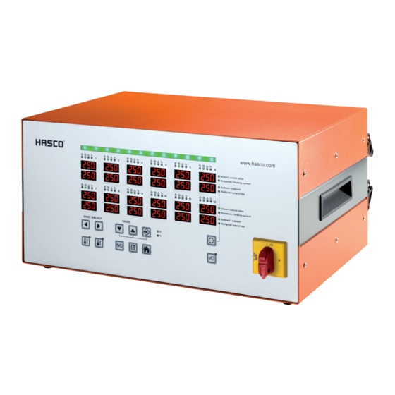
2.2.1 H1252/6x16 Figure 1 - Housing front H1252/6x16 Figure 2 - Housing rear H1252/6x1 8 HASCO hot runner... -
Page 9: H1252/12X16
Instruction manual H1252 2.2.2 H1252/12x16 Figure 3 - Housing front H1252/12x16 Figure 4 - Housing rear H1252/12x16 HASCO hot runner 9... -
Page 10: Technology
The controller displays ‘sensor fracture’ for this channel. 2.3.3 Alarm contact/digital input The H1252 hot runner controllers have a potential-free alarm contact and a digital input that are fed out of the controller via a socket on the rear. The digital input is SPS-compatible, in other words it operates over a voltage range of 13..30 VDC with a typical current consumption of approx. -
Page 11: Pin Assignment
Instruction manual H1252 Digital input 0V reduced- temperature (standby) mode Digital input 24V reduced- temperature (standby) mode 2.3.4 Pin assignment The plug-in connections for the temperature sensors and heating elements are available on the rear of the controller. These correspond to the terminal diagram in Annex 9.1. -
Page 12: Technical Data
16A time-lag (6.3 x 32mm) Power consumption Max. 30 W when idling Thermocouple inputs Thermocouple Fe-CuNi Type J - 0…700°C switchable to NiCr-Ni Type K Cold junction compensation internal Measuring accuracy ±0.25 K Temperature polling 4x128 / second 12 HASCO hot runner... -
Page 13: Commissioning
Before connecting the unit to the mains voltage, a check must be conducted to see that the mains electricity system is correct. The hot runner controllers H1252/6x16 and H1252/12x16 are prepared by default for operation in a star network (3x400VAC + N + PE), but can also be operated in a triangular network (3x230VAC + PE). For operation in a triangular network without a neutral conductor, it is essential to observe the local regulations for the installation of electrical systems. -
Page 14: Operating And Display Elements
Green shows that everything is in order. The controller is operating normally. Yellow indicates warning messages about a deviation from the normal state. Red indicates alarms. Depending on the fault, the outputs of the corresponding zones may be deactivated. 14 HASCO hot runner... - Page 15 Instruction manual H1252 Hand-operated (yellow) Flashing = operated by hand due to incident Regular operation (green) Alarm warning (red) Flashing = alarm Displays the last selected zone Zone selection Each time the arrow buttons are pressed, the display moves on to the next zone.
- Page 16 Basic view: display of all zones/ cancel entry Button for switching the zone display Display: actual value (X) and setpoint value Display: current (I) and output level (Y) Activate/deactivate controller outputs Temperature unit used for display Main switch for switching on the controller. 16 HASCO hot runner...
-
Page 17: Quick Start
Instruction manual H1252 3.3 Quick start 1. Connect up the heating and sensor lines. The plug system assignment is set out in Annex 9.1. 2. Connect up to the mains as per Chapter 3.1 3. Switch on the controller at the main switch 4. -
Page 18: Operation
All other zones that have not been selected are blanked out. 4.1.2 Selecting several zones Step Operation Description Select zone Confirm the zone. … repeat 1 and 2 in order to select any desired zones 18 HASCO hot runner... -
Page 19: Selecting Several Successive Zones
Instruction manual H1252 4.1.3 Selecting several successive zones Step Operation Description Choose the 1st zone that is to be selected. Keep the confirmation button pressed. Each time the button is pressed a zone is added to the zones selected. Release the confirmation button 4.1.4 Selecting all the zones... -
Page 20: Mode Of Operation
Zone off Note: the display flashes and must be confirmed within 5 seconds. Confirmation of the entry made. The display no longer flashes. Press the home button to return to the display of all the zones. 20 HASCO hot runner... -
Page 21: Setpoint Values
Instruction manual H1252 4.3 Setpoint values Step Operation Description Select zone(s) as described under 4.1 Use the buttons to adjust the setpoint value. The display flashes, which means that the value has not yet been adopted. Confirmation of the entry made. -
Page 22: Output Level
The display flashes, which means that the value has not yet been adopted. Confirmation of the entry made. The display no longer flashes. Press the home button to return to the display of all the zones. 22 HASCO hot runner... -
Page 23: Parameters
Instruction manual H1252 4.5 Parameters 4.5.1 Zone parameters Step Operation Description Select zone(s) as described under 4.1 Press the button to go to the parameter setting level Select parameter. Each time an arrow button is pressed, the parameter is increased or reduced. -
Page 24: System Parameters
(default “22”). To do this, set and confirm the current password with the buttons. Following this, the parameter can be changed. The display flashes, which means that the value has not yet been adopted. Example: System parameter with the value 500 24 HASCO hot runner... -
Page 25: Boost
Instruction manual H1252 Confirmation of the entry made. The display no longer flashes. Press the home button to return to the display of all the zones. 4.6 Boost Step Operation Description Select zone(s) as described under 4.1 Pressing the boost button increases the setpoint value for... -
Page 26: Standby
5 Warnings and error messages Unit types H1252/6x16 and H1252/12x16 provide information on the controller's status via a fault-message display and 7- segment display. Warnings and alarms are displayed as abbreviations in the 7-segment display. In addition, the fault-message display (LED strip) indicates the controller status in the colours green, yellow and red. In the normal state, the LED strip is illuminated in green. -
Page 27: Warnings
Instruction manual H1252 5.1 Warnings Warnings are shown in yellow on the fault-message display (LED strip). 7-segm. Alarm · Description/causes display contact strip Positive temperature deviation Active · The actual value for the sensor is above the tolerance band selected as zone parameter... -
Page 28: Alarms
(Lo alarm) Alarm limit (zone parameter is too close to the setpoint value Heating output is possibly insufficient Heating could be defective Sensor not in contact with this zone Sensor reverse polarity Controller is heating 28 HASCO hot runner... - Page 29 Instruction manual H1252 7-segm. Alarm · Description/causes display contact strip Sensor fracture Active · No connection to sensor, also not possible to capture the mean output level so far. If LED strip is see warnings No sensor connected up Sensor leads / connection cable defective...
- Page 30 Wiring error Cable or plug defective Lead is crushed CAN bus malfunction Active · Communication error on the internal I/O boards Identical address allocated twice Cable not connected up correctly Termination resistor missing on last controller 30 HASCO hot runner...
-
Page 31: Functions And Parameter Setting
. The manufacturer must then generate a master password via the displayed PIN. To do this, the service address of HASCO as stated in 1.3 must be contacted. Parameters... -
Page 32: Fahrenheit Display
The controller determines the appropriate control parameters for P, I and D and saves these in parameters This process can be recognised through the flashing green LED strip and, with slow and big objects, can take up to 60s. 32 HASCO hot runner... -
Page 33: Rated Value Output Level
Instruction manual H1252 The classification that is determined can be seen for each zone under parameter Activate and deactivate classification To obtain special settings for the P, I and D parameters in all cases, the classification per zone can be switched off with parameter = “0”. -
Page 34: Heating
Parameter is used to define the allocation of a zone to “combined heating”. Parameters Zone parameters Settings 0: Zone not allocated to combined heating Combined heating 1: Zone allocated to combined heating System parameters Settings 34 HASCO hot runner... -
Page 35: Hot Runner Monitoring
Instruction manual H1252 Maximum temperature Can be set from 1° … 100° difference for combined Standard value: 10° heating Slowest zone Read only Example: Zones 1 to 6 are to be heated together. The temperature difference during heating is to be a maximum of 20°C. Zones 7 and 8 are not to be included in the combined heating. - Page 36 If this value is exceeded, all the zones will be switched off. The following settings must be made: Parameters Zone parameters Settings Lo alarm 150°C Hi alarm 250°C dL / dH 15°C tolerance band System parameters HH alarm 400°C 36 HASCO hot runner...
-
Page 37: Mean Output Level
Instruction manual H1252 The following diagram shows how things fit together: Maximum upper temperature limit of all zones Alarm over-temperature Upper limit tolerance band Setpoint Lower limit tolerance band Alarm under-temperature 6.4.2 Mean output level Description This parameter is calculated during regular operation of the controller. -
Page 38: Monitoring The Heating Current
A defective triac is detected if current is flowing without the outputs being activated. If current is flowing, this zone will be switched off and an error message displayed. 38 HASCO hot runner... -
Page 39: Special Functions
Instruction manual H1252 6.5 Special functions 6.5.1 Temperature increase BOOST Description By executing the boost function, the temperature for selected zones will be increased by a fixed value – the boost offset (parameter ) for a specific time (parameter This is activated via the “boost button”... -
Page 40: Standard Parameters
Brief increase in setpoint temperature by x °C 6.5.1 11 Boost time Temperature increase duration for BOOST 6.5.1 12 Maximum output level Restriction of output level to maximum value 6.2.3 13 Rated value output level Output level set for manual operation 6.2.2 40 HASCO hot runner... -
Page 41: System Parameters
Instruction manual H1252 14 Rated value of current Rated current of zone to be monitored 6.4.4 15 Current tolerance Current monitoring tolerance 6.4.4 16 Standby temperature Temperature to be reduced to a new setpoint value 6.5.2 The mean output level is saved here 17 Mean output level 6.4.2... -
Page 42: Spare Parts + Accessories
The following table contains a list of spare parts that can be replaced if necessary, observing the safety instructions. Spare part Control fuse Control zone fuse 16A gRL I/O board incl. cooling element and triacs Alarm contact / digital input cable Triac 16A 42 HASCO hot runner... -
Page 43: Annex
Instruction manual H1252 9 Annex 9.1 Terminal diagram plug system 6 Zonen gemischt / 6 zones mixed X 1 Kontakt Last Polarität Kontakt Fühler Polarität Contact Load Polarity Contact Sensor Polarity Zone 1 Zone 1 Zone 1 Zone 1 Zone 2... - Page 44 Zone 10 Zone 10 Zone 10 Zone 10 Zone 11 Zone 11 Zone 11 Zone 11 Zone 12 Zone 12 Zone 12 Zone 12 44 HASCO hot runner...
-
Page 45: Clamping Bridges For The Star/Triangle Supply
Instruction manual H1252 9.2 Clamping bridges for the star/triangle supply 9.2.1 Clamping bridges in the star network (state as delivered!) Figure 7 - Star network 9.2.2 Clamping bridges in the triangular network Figure 8 - Triangular network HASCO hot runner 45... - Page 46 07 21 1 i © by HASCO Hasenclever GmbH + Co KG Postfach 1720, D-58467 Lüdenscheid T +49 2351 957-0, F +49 2351 957-237 info@hasco.com, www.hasco.com Subject to technical modifications. Please always check all the data against the product information we publish on the internet.
Need help?
Do you have a question about the H1252 and is the answer not in the manual?
Questions and answers