
Subscribe to Our Youtube Channel
Related Manuals for iPower GXS11301R


Summary of Contents for iPower GXS11301R
- Page 1 PORTABLE GENERATOR Owner’s Manual GXS11301R DO NOT RETURN TO STORE! CALL US FIRST 855-888-3598 FOR SUPPORT Model# 4591003 REV00 Model: Serial: Date Purchased: SAVE THIS MANUAL FOR FUTURE REFERENCE P/N: 32082-00000-00...
-
Page 2: Table Of Contents
Table of Contents Stopping the Engine......20 Introduction..........1 Low Oil Shutdown........21 Safety............1 Do Not Overload Generator....21 General Safety Precautions....2 Maintenance And Storage....22 Safety And Dataplate Labels....7 Maintenance Schedule......22 Unpacking the Generator.......8 Engine Maintenance......22 Parts Included........8 Engine Oil Level Check......22 Assembly..........9 Change Engine Oil........23 Install the Wheel Kit........9 Spark Plug Maintenance.......23 Install the Support Leg......9... -
Page 3: Introduction
Service at 855-888-3598, or which are known to the State of California to cause www.a-ipower.com for starting, operating and cancer and birth defects orother reproductive harm. servicing procedures. The owner is responsible for To minimize exposure, avoid breathing exhaust, and proper maintenance and safe use of the unit. -
Page 4: General Safety Precautions
Asphyxiation Electric Shock Fire Hazard Hazard Hazard Hot Surface. Explosion Moving Parts Do Not Touch the Surface. Hazard Hazard Burn Hazard Operator’s Manual Kickback GENERAL SAFETY PRECAUTIONS • Operate this product ONLY outside and at least 20 feet away from windows, doors and vents to Using a generator indoors CAN KILL YOU IN MINUTES. - Page 5 CORRECT USAGE Example location to reduce risk of carbon monoxide poisoning • Operate generators outside and at least 20 feet away from any structure with exhaust pointed away from doors and windows. at least 20 feet away from windows, doors and vents INCORRECT USAGE Do not operate in any of the following locations: •...
- Page 6 WHEN STARTING EQUIPMENT WARNING • Ensure spark plug, muffler, fuel cap, and air Starter cord kickback (rapid retraction) cleaner are in place. will pull hand and arm toward engine • DO NOT crank engine with spark plug removed. faster than you can let go which could WHEN OPERATING EQUIPMENT cause broken bones, fractures, bruises, or sprains resulting in serious injury.
- Page 7 • It is a violation of California Public Resource Code, DANGER Section 4442, to use or operate the engine on any Contact with terminals, bare wires and forest-covered, brush-covered, or grass-covered electrical connections when generator land unless the exhaust system is equipped with a is running will result in death or serious spark arrester, as defined in Section 4442, injury.
- Page 8 • DO NOT tamper with governor spring, links or other WARNING parts to increase engine speed. Generator supplies Medical and Life Support Uses. correct rated frequency and voltage when running • In case of emergency, call 911 immediately. at governed speed. •...
-
Page 9: Safety And Dataplate Labels
DESCRIPTION CO‐Watch Guard action automatic shutoff *See CO Watch Guard action section Carbon Monoxide Fuel Safety Symbols Hot Surface GXS11301R MODEL NO.: 4591003 REV 00 Rated Voltage: 120V/240V Energy Efficiency: (at nominal operating conditions) Rated Frequency: 60Hz Rated Amperage: 75A/37.5A... -
Page 10: Unpacking The Generator
UNPACKING THE GENERATOR • Open carton completly. Remove and verify carton content prior to assembly. Your generator ships with following items. • Call our customer service at 855-888-3598 with the unit model and serial number for any missing item. • Record model, serial number, and date of purchase on front cover of this munual for your own record. -
Page 11: Assembly
ASSEMBLY Your generator requires some assembly prior to usage. CAUTION Assembly the generator will require lifting the unit. Always have assistance when lifting the generaotor. WARNING Do not plug in or turn on the generator until it is fully 뇈샽 25.400 assembled according to the instructions. - Page 12 ASSEMBLY NOTICE The generator is equipped with a battery charging feauture. Once the engine is running,a small charge will slowly recharge the battery. If you do not plan to use the generator for a long period of time,we recommend to DISCONNECT the battery plugs A and B to protect the battery from losing charge,You may also to use a battery float charger (not included) to maintain battery...
-
Page 13: Controls And Features
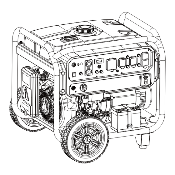
CONTROLS AND FEATURES 9 10 1 - Frame 9 - Engine 2 - Fuel Gauge 10 - Recoil Starter 3 - Control Panel 11 - Starting Dial Switch 4- Alternator Cover 12 - Battery 5 - Fuel Tank 13 - Remote Holder 6 - Fuel Cap 14 - Support Leg 7 - Spark Plug... -
Page 14: Control Panel Features
CONTROL PANEL FEATURES 1. Push-Button START/STOP: Push once to automati- 8. Circuit Breaker(AC): Protects the generator cally start the engine. Push again to stop the engine. against electrical overloads. 2. CO (Carbon Monoxide) WATCH-GUARD 9. 120V AC, 20A Duplex, GFCI, Single Phase, 60 Indicator Light (Red for Shut off and Yellow for Hz Outlets (5-20R): Each outlet is capable of Service): The CO(Carbon Monoxide) WATCH-GUARD... -
Page 15: Specifications
SPECIFICATIONS Generator Specifications Model GXS5001 GXS11301R Starting current 41.7A 94.2A/47.1A Year of manufacture 2024 2024 Reference number of the standards applied ISO/8528 Standards ISO/8528 Standards Rotation speed 3600rpm 3600rpm Maximum ambient temperature 40°C/104°F 40°C/104°F Minimum ambient temperature (-5)°C/23°F (-5)°C/23°F Thermal rating or heating 45°C/113°F... -
Page 16: Co Watch-Guard
2-Blinking Yellow Light provides notification that a CO WATCH-GUARD fault has occurred and no longer provides protection. The generator is shutoff automatically and the yellow light will blink for at least five minutes after shutoff. Call A-iPower Customer Service 855-888-3598 for repair. - Page 17 sensor is working properly. The CO WATCH-GUARD must only be serviced by qualified technician to restore it to original settings. WARNING DO NOT modify or tamper with the Carbon Monoxide Detecting System (CO WATCH-GUARD). Not following these instructions could result in death or serious injury due to Carbon Monoxide detecting system malfunction. CO WATCH-GUARD will detect the accumulation of carbon monoxide from other fuel burning sources such as engine powered tools used in the area of operation.
-
Page 18: Add Engine Oil
Add Engine Oil NOTICE We recommend using SAE 10W-30 APISJ oil for We consider the first 5 hours of run time to be the best performance. Other high-quality detergent oils break-in period for the unit. During the break in (APISJ or higher) are acceptable. Do not use special period stay at or below 50% of the running watt additives. -
Page 19: Operation At High Altitude
To operate at high altitudes A-iPower • If fuel spills, wait until it evaporates before starting can provide a high altitude carburetor main jet. The engine. -
Page 20: Operation
OPERATION Generator Location Surge suppressors come in single- or multi-outlet styles. They’re designed to protect against virtually WARNING all short-duration voltage fluctuations. Make sure you review each warning in order to For Cold Weather Starting prevent fire hazard. • While you must run your generator outside, you may keep the generator in a covered area to Using a generator indoors CAN KILL YOU IN MINUTES. - Page 21 4. Add gasoline to the fuel tank. Electric 7. Recoil start Move the choke lever to 5. Turn the battery switch to the “ON”(l) position. the “START” position. Pull recoil starter slowly until resistance is felt, then pull rapidly. 6. Turn the starting dial switch to the “RUN” position.
-
Page 22: Connecting Electrical Loads
crankcase. This unit may be equipped with a low oil 2. Push STOP on the remote protection device. If so, oil must be at proper level start key fob for 3 seconds. for engine to start. Connecting Electrical Loads This unit has been pretested and adjusted to handle its full capacity. -
Page 23: Low Oil Shutdown
WARNING Fuel and its vapors are extremely flammable and explosive which could cause burns, fire or explosion resulting in death or serious injury. DO NOT stop engine by moving choke control to “START” position. NOTE: Always ensure that the fuel valve is in the “OFF” position when the engine is not in use. -
Page 24: Maintenance And Storage
MAINTENANCE AND STORAGE MAINTENANCE SCHEDULE NOTE: Maintenance should be performed more frequently Regular Maintenance will improve the performance when generator is used in dusty areas. and extend the life of your generator. Follow When generator has exceeded the maximum figures maintenance schedule intervals whichever occurs specified in the table, maintenance should still be first according to use. -
Page 25: Change Engine Oil
Recommended Engine Oil Type CAUTION 10W-30 Avoid prolonged or repeated skin contact with used motor oil. 5W-30 10W-40 1. Remove the oil cap (A) and wipe dipstick clean. 5W-30 Full Synthetic 2. Place a container underneath the oil drain plug to °F collect used lubricant as it drains. -
Page 26: Air Filter Maintenance
7. Tighten with wrench to compress washer. If spark Battery Replacement plug is new, use 1/2 turn to compress washer WARNING appropriate amount. If reusing old spark plug, use 1/8 to 1/4 turn for proper washer compression. Burn hazard. The battery contains sulfuric acid NOTE: (electrolyte) which is highly corrosive and poisonous. -
Page 27: Cleaning The Spark Arrestor
Cleaning the Spark Arrestor Intake Valve Exhaust Valve Valve 1. Allow the engine to cool completely before 0.004~0.006 inch 0.006~0.008 inch Clearance servicing the spark arrestor. 0.1~0.15 mm 0.15~0.2 mm 2. Loosen the screw (A) to be able to remove Torque 10-12 N·M 10-12 N·M... - Page 28 Long Term Storage (over one year) DRAINING THE FLOAT BOWL For long term storage, the gasoline tank and 1. Turn the fuel tank valve to the OFF position. carburetor must be drained of gasoline. 2. Locate the drain screw on the bottom of the 1 - After engine cools down, remove all gasoline carburetor float bowl.
-
Page 29: Trouble Shooting
TROUBLE SHOOTING PROBLEM POSSIBLE CAUSE SOLUTION Engine is running, 1. AC Circuit breaker is open. 1. Check AC load and reset circuit breaker. but no AC output is 2. Fault in generator. 2. Contact customer service or authorized service center. available. -
Page 30: Parts Diagram And Parts List
PARTS DIAGRAM AND PARTS LIST GXS11301R PARTS DIAGRAM Page 28... -
Page 31: Parts List
Parts List Part Number Description Qty. Part Number Description Qty. 30101-00326-00 Screw(M5*12) 30136-00086-00 Flat washer 33082-00162-00 End cover 34006-00020-00 Clip 20044-00104-00 33126-00008-00 Plug 30101-00329-00 Screw(M5*16) 33580-00035-00 Handle fixing pin 30101-00110-00 Screw(M10*285) 20135-00470-00 Handle assembly 30136-00016-00 Flat washer 33015-00012-00 Handle rubber sleeve 33004-00017-00 Bracket 30125-00026-00... - Page 32 Part Number Description Qty. 33369-00404-00 Panel seat 33368-02642-01 Panel 31038-00023-00 Circuit breaker(AC) 31038-00053-00 Circuit breaker(AC) 30101-01133-00 Grounding terminal 31038-00083-00 Circuit breaker(AC) 31026-00320-00 Remote set up button 31008-00048-02 Hour meter 31038-00036-00 Circuit breaker(DC) 20270-00003-00 Low oil indicator light 20270-00015-01 CO WATCH-GUARD indicator light 31026-00459-00 Push button 31042-00226-02...
- Page 33 PARTS DIAGRAM (ENGINE) Page 31...
- Page 34 Parts List Part Number Description Qty. Part Number Description Qty. 30101-00071-00 Screw(M6*12) 34004-00018-00 Piston 20021-00018-00 Valve cover 34006-00015-00 Piston pin 33048-00154-00 Valve cover gasket 30150-00023-00 Piston pin clip 34019-00076-00 Rocker arm 20008-00009-00 Connecting rod assembly 34016-00009-00 Valve collet 30101-00514-00 Screw(M12*16) 34016-00005-00 Valve spring seat 30136-00080-00...
- Page 35 Part Number Description Qty. 20009-00027-00 Charging coil components 33593-00007-00 Wire press plate 30101-00070-00 Screw(M6*12) 30101-00530-00 Screw(M6*30) 34026-00008-00 Governor linkage 34015-00010-00 Governor spring 34025-00007-00 Governor lever 34015-00021-00 Return spring 20022-00018-00 Governor assembly 30101-00070-00 Screw(M6*12) 20149-00016-00 Starter assembly 30101-00461-00 Screw(M8*32) 34023-00445-00 Fuel hose 34024-00022-00 Clamp(B8) 34023-00074-00...
-
Page 36: Circuit Diagram
Circuit Diagram Page 34... -
Page 37: Warranty
Warranty Term ups resulting from improper maintenance. A-iPower will provide warranty for any of its products Additional exclusions - this warranty does not cover purchased through any authorized AiPower dealer in wearable parts such as filers, spark plugs, o-rings, North America to the original purchaser and will be batteries etc. - Page 38 Warranty limits and Implications and Consequential Damages A-iPower is not obligated to cover any loss of time, use of product, freight cost, or any other incidental or consequential claim from the use of this product. This warranty is in Lieu of all other warranties, express or implied.
- Page 39 Fontana, CA 92337 USA Phone: 855-888-3598 support@a-ipower.com www.a-ipower.com...
- Page 40 Features Product Appearance Warranty Ease of Maintenance Noise Level 5 . HOW LIKELY ARE YOU TO RECOMMEND A-iPOWER TO FAMILY OR FRIENDS? Extremely Not Likely Likely at all Privacy Statement: A-ipower is committed to respecting your privacy and to complying with the regulations regarding the protection of personal data.
- Page 41 Fontana, CA 92337 USA Phone: 855-888-3598 support@a-ipower.com www.a-ipower.com...
Need help?
Do you have a question about the GXS11301R and is the answer not in the manual?
Questions and answers