Table of Contents
Advertisement
Quick Links
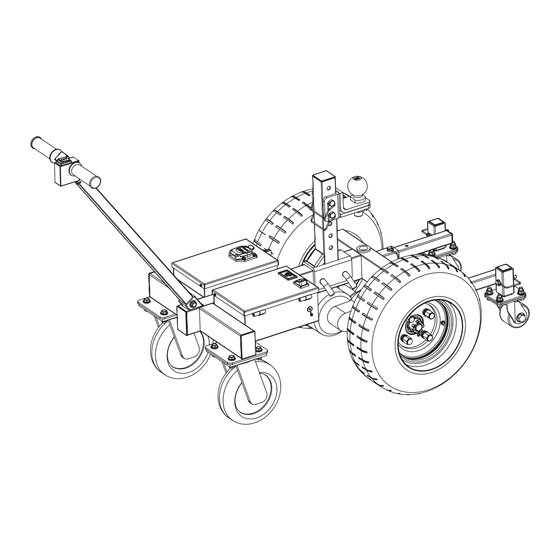
Electric Power Dolly
Operator's Manual
WARNING:
Read carefully and understand all INSTRUCTIONS before operating. Failure to follow the safety
rules and other basic safety precautions may result in serious personal injury.
Save these instructions in a safe place and on hand so that they can be read when required.
Keep these instructions to assist in future servicing.
REV 1.1
Advertisement
Table of Contents

Related Manuals for Super Handy GUO094


Summary of Contents for Super Handy GUO094
- Page 1 Electric Power Dolly Operator's Manual WARNING: Read carefully and understand all INSTRUCTIONS before operating. Failure to follow the safety rules and other basic safety precautions may result in serious personal injury. Save these instructions in a safe place and on hand so that they can be read when required. Keep these instructions to assist in future servicing.
-
Page 2: Table Of Contents
INDEX 1. WARNING -------------------------------------------------------------------------------- 1 2. TECHNICAL SPECIFICATIONS ---------------------------------------------------- 2 3. MAIN COMPONENTS ----------------------------------------------------------------- 3 4. ASSEMBLY --------------------------------------------------------------------------- 4~5 5. OPERATION -------------------------------------------------------------------------- 6~8 6. SERVICE GUIDE ------------------------------------------------------------------ 8~11 7. MAINTENANCE AND STORAGE ------------------------------------------------ 12 8. WARRANTY --------------------------------------------------------------------------- 12 9. TROUBLE SHOOTING ------------------------------------------------------------- 12 10. -
Page 3: Warning
1. WARNING DO NOT USE THIS PRODUCT TO MOVE TRAILER LOADED OR UNLOADED ACROSS ANYTHING OTHER THAN LEVEL PAVED SURFACES WITH LESS THAN A 4° GRADE. DO NOT USE ON A SLOPED DRIVEWAY. DO NOT ATTEMPT TO USE THIS PRODUCT ON A BOAT LAUNCH. THIS PRODUCT IS NOT INTENDED TO REPLACE YOUR VEHICLE. -
Page 4: Technical Specifications
RVs, etc. equipped with ball head couplings. It has the functions of forward, backward and basic steering. It is intended for movement of trailers over short distances or in compact confined spaces. GUO094 Description Electric Power Dolly... -
Page 5: Main Components
3. MAIN COMPONENTS 1. Start switch: Control the dolly to move "forward" or "backward" 2. Transformer: Voltage conversion, 24V to 12V 3. Controller: A device to preset instructions 4. 7-core socket: Provide 12V power supply to the electromagnetic brake or lift 5. -
Page 6: Assembly
4. ASSEMBLY Fig. 3 1. Installation of the handle bar assembly (See Fig.3) Open the lid of the control box, thread the handle assembly lead through the square opening at the front of the frame (Step 1) and lead it out through the large round hole on the side of the control box (Step 2). - Page 7 4. Installation of the rear support assembly Fig. 6 (See Fig.6) Insert the two rear support assemblies into the square holes of the frame respectively (Step 1), align the holes at the right positions and insert the 8×60 square pins for fixation (Step 2). 5.
-
Page 8: Operation
5. OPERATION Commissioning and preparations 1. Before operation, check that all bolts are securely tightened, and the hitch ball stem is Secure- ly fastened to your desired position and locked. 2. Make sure that the tires are not cracked, bulging or otherwise defective, and that the tire pressure is maintained at 60±2psi (4.2±0.1kgs/cm²). - Page 9 3. The rear support wheel assembly is intended Fig. 10 to provide support and increased stability during towing., and according to the road conditions, can position can be adjusted up and down as well as forward and backwards relative to the main wheels. DO NOT operate trailer dolly without the support wheel assem- bly properly attached and secured in place.
-
Page 10: Service Guide
3. Shut down the power after use. And park the dolly in the correct position. Please maintain the battery charge level. BATTERY CHARGE LEVEL MUST BE MAINITAINED REGUALRLY OTHERWISE THE LEAD ACID BATTERY MAY BECOME FULLY DISCHARGED, RESULTING IN DAMAGE TO THE BATTERY OR FAILRE FOR IT TO MAINTAIN ANY CHARGE. - Page 11 Replacement of the power wheels Fig. 15 a. Remove the four M14 nuts (S/N 7) and knock the power wheel down alternately with a soft hammer from left to right (S/N 8). (See Fig.15) Remove nuts Remove the wheel b. With the inflating inlet of the power wheel Fig.
- Page 12 b. Installation of the controller. Insert the Fig. 18 controller into the box compartment, connect the corresponding color wires and controller terminals according to the diagrams (Figure a, Figure b and Figure c), close the box lid and tighten the screws on both sides. (See Fig.18) (a) Connect with the rear axle (a) Connect with the rear axle...
- Page 13 b. Align the power switch with the square hole of Step 1 the lid and press it directly to the bottom (Step 1), make sure the snap feet is secured firmly, insert the terminals according to the electrical diagram, and then turn on the power after confirming that it is correct (Step 2).
-
Page 14: Maintenance And Storage
7. MAINTENANCE AND STORAGE 1. For storage, the product shall be stored in a cool, dry and dust-free place, to avoid direct sunlight and rain. 2. During the transportation, loading and unloading of the product, it is prohibited to cast, drop, throw, trample and perform other barbaric operations on the product. - Page 15 Part No. Description Q’ty Part No. Description Q’ty Handle sleeve Square pin Start switch Switch box Washer Handle bar assembly Pin assembly Hex nut M24×3 Rear axle 24V 800W Split pin 4×50 DC socket Nut M14×1.5 Battery box assembly Power wheel 16.5×6.5-8 Power switch Controller 24v 800w Voltage and battery level indicator...
- Page 16 Great Circle USA Support Line: 1-866-493-0524 help@greatcircleus.com www.greatcircleus.com Size: 145x210mm 157克双铜 REV 10/09/22 6.02.00011...
Need help?
Do you have a question about the GUO094 and is the answer not in the manual?
Questions and answers