
Related Manuals for KEB DYNAMIC LINE 4


Summary of Contents for KEB DYNAMIC LINE 4
- Page 1 DYNAMIC LINE 4 INSTRUCTIONS FOR USE | INSTALLATION SERVO MOTORS DL4 SIZE SE...SG Translation of original manual Document 20220629 EN 05...
-
Page 3: Preface
The hardware and software described in this document are products of KEB. The infor- mation contained in this document is valid at the time of publishing. KEB reserves the right to update this document in response to misprints, mistakes or technical changes. -
Page 4: Laws And Guidelines
The customer may use the instructions for use as well as further documents or parts from it for internal purposes. Copyrights are with KEB and remain valid in its entirety. This KEB product or parts thereof may contain third-party software, including free and/ or open source software. -
Page 5: Table Of Contents
TAbLE Of cONTENTS Table of contents Preface ..............................3 Signal words and symbols ......................3 More symbols ..........................3 Laws and guidelines ........................4 Warranty and liability ........................4 Support ............................4 Copyright ............................4 Table of contents ........................... 5 List of figures ............................8 List of Tables ............................ - Page 6 TAbLE Of cONTENTS 2.7.4 Speed and shaft position measuring system ..............25 2.7.5 Temperature monitoring ..................... 25 2.7.6 Temperature sensor Pt1000 ....................26 2.7.7 Deep groove ball bearing ....................27 2.7.7.1 Initial start-up of deep groove ball bearings ..............27 3 Operating conditions ...........
- Page 7 TAbLE Of cONTENTS 5.6.1 Technical data of the holding brake SF CF ................ 58 5.6.2 Dimensions servo motors SF CF ..................58 5.7 Technical data servo motors SG cS .................... 59 5.7.1 Technical data of the holding brake SG CS ................ 62 5.7.2 Dimensions servo motors SG CS (exclusive SG CS L8 SP30) .........
-
Page 8: List Of Figures
LIST Of fIGURES List of figures Figure 1: Nameplate example ......................20 Figure 2: General speed-torque characteristic ................21 Figure 3: Example image of a motor ....................23 Figure 4: Varistor protective wiring ....................24 Figure 5: Temperature sensor Pt1000..................... 26 Figure 6: Derating of the motor depending on temperature / altitude .......... -
Page 9: List Of Tables
LIST Of TAbLES List of Tables Table 1: Type code ........................19 Table 2: Configurable options ......................19 Table 3: Rated material number ....................20 Table 4: Temperature sensor Pt1000..................... 26 Table 5: Value table temperature sensor Pt1000 ................26 Table 6: Product features.......................28 Table 7: Ambient conditions......................29 Table 8:... -
Page 10: Glossary
Incremental signal with an output voltage (up to 30V) -> TTL International standard IP xx Degree of protection (xx for level) KEB product The KEB product is subject of this manual. Silicium temperature sensor (pola- rized) Manufacturer The manufacturer is KEB, unless otherwise specified (e.g. as ma-... -
Page 11: General Standards
GENERAL STANDARDS General standards DGUV regulation 3 Electrical installations and equipment DIN 46228-1 Tubular end-sleeves without plastic sleeve DIN 46228-4 Tubular end-sleeves with plastic sleeve DIN IEC 60364-5-54 Low-voltage electrical installations - Part 5-54: Selection and erection of electrical equipment - Earthing arrangements, protective conductors and protec- tive bonding conductors EN 60204-1 Safety of machinery - Electrical equipment of machines - Part 1: General requi-... -
Page 12: Standards For Asynchronous And Synchronous Motors
STANDARDS fOR ASyNchRONOUS AND SyNchRONOUS MOTORS Standards for asynchronous and synchronous motors EN 60034-1 Rotating electrical machines - Part 1: Rating and performance (IEC 2/1768/CD) EN 60034-2-3 Rotating electrical machines - Part 2-3: Specific test methods for determining losses and efficiency of converter-fed AC motors (IEC 2/1841/CD) EN 60034-5 Rotating electrical machines - Part 5: Degrees of protection provided by integral design of rotating electrical machines (IP code) - Classification (IEC 60034-5) EN 60034-6 Rotating electrical machines - Part 6: Methods of cooling (IC-Code) (IEC 60034-6) -
Page 13: Basic Safety Instructions
Hazards and risks through ignorance! ► Read the instructions for use! ► Observe the safety and warning instructions! ► If anything is unclear, please contact KEB Automation KG! 1.1 Target group This instruction manual is determined exclusively for electrical personnel. Electrical per- sonnel for the purpose of this instruction manual must have the following qualifications: •... -
Page 14: Installation
bASIc SAfETy INSTRUcTIONS To prevent damage to the motor: • Check if necessary and do not remove anti-corrosive coat at the shaft ends, flange surfaces etc. • No vibrations may occur in the storage location. • In case of storage longer than 3 months, rotate the motor in both directions at a slow speed (<... -
Page 15: Connection Instructions
1.4.1 EMc-compatible installation Observance of the limit values required by EMC law is the responsibility of the customer. Notes on EMC-compatible installation in conjunction with drive controllers can be found here. www.keb.de/fileadmin/media/Manuals/emv/0000neb0000.pdf... -
Page 16: Start-Up And Operation
bASIc SAfETy INSTRUcTIONS 1.5 Start-up and operation The start-up (i.e. for the specified application) is forbidden until it is determined that the installation complies with the machine directive; account is to be taken of EN 60204-1. WARNING Software protection and programming! Hazards caused by unintentional behavior of the drive! ► Check especially during initial start-up or replacement of the drive controller if parameterization is compatible to application. ►... -
Page 17: Repair
1.8 Disposal Electronic devices of the KEB Automation KG are exclusively professional devices for further industrial processing (so-called B2B devices). Manufacturers of B2B devices are obliged to take back and recycle devices manufac- tured after 14.08.2018. -
Page 18: Product Description
The servo motors of the DL4 series are 8-pole permanent-field synchronous motors with a sine-wave inducted voltage. 2.1 Specified application The KEB synchronous servo motors are exclusively designed for the operation at digital servo controllers. They are intended for industrial systems only. They comply with the harmonised standards of the series EN 60034-1/ VDE 0530. -
Page 19: Type Code
PRODUcT DEScRIPTION 2.3 Type code 0 0 SM 0 0 0 - c M A T Execution code Table 1: Type code 2.3.1 Configurable options x x S x L x c x S P x x - f K x b r x E N c 0 x O P 0 x OP00: Without OP01:... -
Page 20: Rated Material Number
Configured material Configurable material Table 3: Rated material number 2.4 Nameplate µABCDEFG/001ÍÄ S/N ABCDEFG/001 - yyyy/ww 2022/48 Mat. No.: Made in Italy Type: KEB Automation KG D-32683 Barntrup www.keb.de E471175 BCode BR V941042WN1340C001 Brushless Servomotor Duty N [rpm] 0 [Nm] N [Nm]... -
Page 21: General Speed-Torque Characteristic
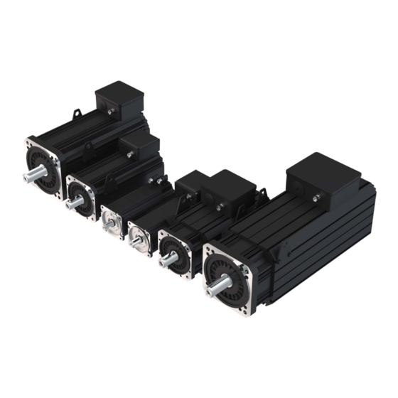
PRODUcT DEScRIPTION 2.5 General speed-torque characteristic Definition characteristic Stall torque (n=0) Max. torque _max Rated torque Rated speed Max. speed _max _max DC link voltage Figure 2: General speed-torque characteristic 2.6 General project design 2.6.1 Selection of the servo motor Calculate the following values before you selection the servo motor: •... -
Page 22: Selection Of The Servo Controller
PRODUcT DEScRIPTION 2.6.2 Selection of the servo controller The selection of the servo controller occurs via the max. short time current and the rated output current. • standstill continuous current (I L_max Max. short time –––––––––––––––––––––––––––––––––– current Stall torque (M effective torque (M ) •... -
Page 23: Construction And Definition
PRODUcT DEScRIPTION 2.7 Construction and definition 2.7.1 Drive end and direction of rotation Drive end of the motor View 60034-7 the two ends of a motor are defined as follows: D (Drive End): Drive end (AS) of the motor. N (Non-Drive End): Non-drive end (BS) of the motor. Direction of rotation of the motor When the motor terminals U1, V1, W1 are connect- ed to the drive controller output with U, V, W (with... -
Page 24: Figure 4: Varistor Protective Wiring
PRODUcT DEScRIPTION NOTICE Do not use the holding brake as a working brake! Brake failure due to overload! ► Check the proper functioning of the brake (optional) after installing the motor. ► The optional holding brake is only designed for a limited number of emergency brakings. -
Page 25: Speed And Shaft Position Measuring System
PRODUcT DEScRIPTION 2.7.4 Speed and shaft position measuring system The motors are equipped with a resolver, Sick Stegmann Hiperface Singleturn or Sick Stegmann Hiperface Multiturn for speed and shaft position control. WARNING Adjustment of the measuring system! Injuries due to uncontrolled motor reactions! ►... -
Page 26: Temperature Sensor Pt1000
PRODUcT DEScRIPTION 2.7.6 Temperature sensor Pt1000 Pt1000 temperature sensor RTD (Platinum Resistance Temperature Sensor type Detectors) Reference standard DIN EN 60751 Degree of precision Class B ΔT ± (0.3+0.005T) °C R (0 °C) = 1000 Ω Table 4: Temperature sensor Pt1000 1800 1600 1400 1200 1000 Temperature in °C Figure 5: Temperature sensor Pt1000 Temperature... -
Page 27: Deep Groove Ball Bearing
PRODUcT DEScRIPTION 2.7.7 Deep groove ball bearing The used deep groove ball bearings are suitable for high speeds and are lubricated with special greases that are resistant against high temperatures. 2.7.7.1 Initial start-up of deep groove ball bearings When starting the motor for the first time, we recommend running in the bearings as follows: ►... -
Page 28: Operating Conditions
OPERATING cONDITIONS 3 Operating conditions 3.1 Product features of the DL4 servo motors feature Standard Option Type IM B5 Foot / flange IM B3 / IM B35 IP65 - with shaft sealing ring D-side Degree of protection IP54 - motor IP44 - fan Motor type Permanent magnet synchronous servo motor Nominal rating Valid for S1 operation (if not marked otherwise) Vibration severity level... -
Page 29: Ambient Conditions
OPERATING cONDITIONS 3.2 Ambient conditions If the ambient conditions are incorrect, the power and torque of the motors may deviate from the specified values. Storage Ambient temperature -20 °C...70 °C Operation Ambient temperature without brake -20 °C...40 °C Ambient temperature with brake 2 °C...40 °C Relative humidity <... -
Page 30: Derating Of The Motor Depending On Temperature / Altitude
OPERATING cONDITIONS 3.3 Derating of the motor depending on temperature / altitude Altitude in m Figure 6: Derating of the motor depending on temperature / altitude 3.4 Test flange for thermal determinations The rated power (rated torque) applies for continuous operation (duty type S1) at ambi- ent temperature of 20°C; tolerance ± 10 %. -
Page 31: Degree Of Protection Of Servo Motors
OPERATING cONDITIONS 3.5 Degree of protection of servo motors The housings of the servo motors DL4 series are generally designed to meet the de- gree of protection IP54 as specified in 60034-5. See table below for the respective sealing. Degree of pro- Shaft sealing User information tection The effect to moisture in the shaft and Standard... -
Page 32: Connection
cONNEcTION 4 connection The connection must be carried out in such a way that a permanently safe, electrical connection is maintained. 4.1 DL4 motor with flange sockets (SE CS) By manually turning the flange sockets any outgoing cable direction can be adjusted in the range of 300°. In addition, there are four locking points at 90°. Figure 7: Top view of a DL4 motor with flange sockets 4.2 DL4 motor with terminal box (SE cf, Sf...SG) -
Page 33: Connectors
cONNEcTION 4.3 connectors Motor size SE cS Encoder connection Motor connection Motor size SE cf, Sf...SG Encoder connection Motor connection Figure 9: Connectors with a view to the connection pins at the motor For motors without encoder system (e.g. for encoderless SCL operation) the complete encoder connection is not required. -
Page 34: Motor Connection
cONNEcTION 4.4 Motor connection 4.4.1 Motor size SE cS Motor size SE cS connection Signal Motor phase U Motor phase V Motor phase W Protective earth Brake + Brake - Temperature sensor + Temperature sensor - Figure 10: Motor connection motor size SE CS Drive controller series Required motor cable 1.5 mm²:... -
Page 35: Motor Size Se Cf, Sf
cONNEcTION 4.4.2 Motor size SE cf, Sf...SG Motor size SE cf, Sf...SG ④ ⑥ ⑧ ① ② ③ ⑤ ⑦ ⑨ ⑩ Legend Motor phase W Brake + (option) Motor phase V Brake - (option) Motor phase U Additional fan (option) Temperature sensor (Pt1000) 10 Protective earth Figure 11: Motor connection motor size SE CF, SF...SG... -
Page 36: Connection Data Motor Size Se Cf, Sf
cONNEcTION 4.4.2.1 Connection data motor size SE CF, SF...SG cross-section Speed connection terminals Motor type in rpm 1...3 4...9 SE CF L2...L8 1500...3000 SF CS L2...L8 1000...3000 1000 2000 3000 1000 2000 3000 SF CF 1000 2000 3000 1000 2000 3000 1000 2000... -
Page 37: Tightening Torques
cONNEcTION 4.4.2.2 Tightening torques connection size Tightening torque in Nm Table 12: Tightening torques 4.4.3 Auxiliary fan (optional) Externally cooled motors can optionally be equipped with an additional electric fan. The auxiliary fan must be externally supplied with voltage and switched on. The fan is mount- ed opposite the coupling side to ensure axial ventilation. -
Page 38: Encoder Connection
cONNEcTION 4.5 Encoder connection WARNING Subsequent adjustment of the measuring system! Malfunction and uncontrolled reactions of the motor! ► The measuring system of the synchronous motors is factory-adjust- ed to the respective drive controller. Any mis-adjustment may lead to uncontrolled motor response or complete failure of the motor. ►... -
Page 39: Hiperface Terminal Assignment
cONNEcTION 4.5.2 hiperface terminal assignment Description View Pin No. Signal colour REF_SIN- REF_COS- yellow Data+ grey Data- pink SIN+ blue COS+ green +7.5 V brown View to the white connector pins of the resolver connector at the motor All unspecified contacts are not assigned. Figure 13: Hiperface terminal assignment Drive controller series Required encoder cable... -
Page 40: Technical Data
TEchNIcAL DATA 5 Technical Data 5.1 Permissible axial and radial forces The maximum permissible axial and radial forces must not be exceeded in order to ensure smooth running of the motor. • The forces charge the mid-shaft end. • The radial forces F are depending on the speed n •... -
Page 41: Maximum Radial Forces
TEchNIcAL DATA 5.1.2 Maximum radial forces Motor type SE L2...L6 (bearing type DE / NDE: 6206 ZZ / 6205 ZZ) Speed / rpm Length x in mm 1000 1500 2000 2500 3000 2300 2300 1825 1442 1256 1139 43.75 2300 2300 1887 1492... -
Page 42: Shaft End
TEchNIcAL DATA Motor type SG (bearing type DE / NDE: 6313 ZZ NR / 6309 ZZ) Speed / rpm Length x in mm 1000 1500 2000 2500 3000 7450 7450 7450 6561 5721 5190 4523 4102 3802 3573 96.25 7450 7450 7450 6822... -
Page 43: Technical Data Servo Motors Se Cs
TEchNIcAL DATA 5.3 Technical data servo motors SE cS The torque values refer to a motor flanged in horizontal position (steel flange dimensions 500 x 500 x 40 mm). Min. PWM 8kHz, DC link voltage DC 560 V. Motor size SE-cS-SP15 Length cooling Self-cooling Rated speed / rpm 1500 Max. speed / rpm 6000 Mech _max... -
Page 44: Table 21: Technical Data Servo Motors Se-Cs-Sp20
TEchNIcAL DATA Motor size SE-cS-SP20 Length cooling Self-cooling Rated speed / rpm 2000 Max. speed / rpm 6000 Mech _max Rated voltage Stall torque / Nm 11.6 38.7 Current at stall torque 12.4 15.9 Rated power / kW Rated current 12.9 Rated torque / Nm... -
Page 45: Table 22: Technical Data Servo Motors Se-Cs-Sp30
TEchNIcAL DATA Motor size SE-cS-SP30 Length cooling Self-cooling Rated speed / rpm 3000 Max. speed / rpm 6000 Mech _max Rated voltage Stall torque / Nm 11.6 38.7 Current at stall torque 13.4 18.2 23.5 Rated power / kW Rated current 10.3 12.5 13.9... -
Page 46: Technical Data Of The Holding Brake Se Cs
TEchNIcAL DATA 5.3.1 Technical data of the holding brake SE CS Motor size SE cS Holding torque at 100 °C / Nm Rated voltage 24 ± 5 % Br_dc Holding voltage HS_dc Power input at 24V Brake closing time / ms ≤ 35 Brake release time / ms... -
Page 47: Technical Data Servo Motors Se Cf
TEchNIcAL DATA 5.4 Technical data servo motors SE cf The torque values refer to a motor flanged in horizontal position (steel flange dimensions 500 x 500 x 40 mm). Min. PWM 8kHz, DC link voltage DC 560 V. Motor size SE-cf-SP15 Length cooling Separate cooling Rated speed / rpm 1500 Max. speed / rpm 6000 Mech _max... -
Page 48: Table 25: Technical Data Servo Motors Se-Cf-Sp20
TEchNIcAL DATA Motor size SE-cf-SP20 Length cooling Separate cooling Rated speed / rpm 2000 Max. speed / rpm 6000 Mech _max Rated voltage Stall torque / Nm 15.4 Current at stall torque 12.7 17.4 22.1 Rated power / kW Rated current 11.9 16.1 Rated torque... -
Page 49: Table 26: Technical Data Servo Motors Se-Cf-Sp30
TEchNIcAL DATA Motor size SE-cf-SP30 Length cooling Separate cooling Rated speed / rpm 3000 Max. speed / rpm 6000 Mech _max Rated voltage Stall torque / Nm 15.4 Current at stall torque 18.6 25.3 32.5 Rated power / kW 10.4 12.3 Rated current 20.6... -
Page 50: Technical Data Of The Holding Brake Se Cf
TEchNIcAL DATA 5.4.1 Technical data of the holding brake SE CF Motor size SE cf Holding torque at 100 °C / Nm Rated voltage 24 ± 5 % Br_dc Holding voltage HS_dc Power input at 24V Brake closing time / ms ≤ 35 Brake release time / ms... -
Page 51: Technical Data Servo Motors Sf Cs
TEchNIcAL DATA 5.5 Technical data servo motors Sf cS The torque values refer to a motor flanged in horizontal position (steel flange dimensions 500 x 500 x 40 mm). Min. PWM 8kHz, DC link voltage DC 560 V. Motor size Sf-cS-SP10 Length cooling Self-cooling Rated speed / rpm 1000 Max. speed / rpm 6000 Mech _max... -
Page 52: Table 29: Technical Data Servo Motors Sf-Cs-Sp20
TEchNIcAL DATA Motor size Sf-cS-SP20 Length cooling Self-cooling Rated speed / rpm 2000 Max. speed / rpm 6000 Mech _max Rated voltage Stall torque / Nm Current at stall torque 14.8 25.6 37.3 43.5 Rated power / kW 10.7 Rated current 14.3 22.4 33.5... -
Page 53: Table 30: Technical Data Servo Motors Sf-Cs-Sp30
TEchNIcAL DATA Motor size Sf-cS-SP30 Length cooling Self-cooling Rated speed / rpm 3000 Max. speed / rpm 6000 Mech _max Rated voltage Stall torque / Nm Current at stall torque 20.2 40.9 46.6 Rated power / kW 13.8 16.7 20.4 Rated current 18.8 30.9... -
Page 54: Technical Data Of The Holding Brake Sf Cs
TEchNIcAL DATA 5.5.1 Technical data of the holding brake SF CS Motor size Sf cS Holding torque at 100 °C / Nm Rated voltage 24 ± 5 % Br_dc Holding voltage HS_dc Power input at 24V Brake closing time / ms ≤ 100 Brake release time / ms... -
Page 55: Technical Data Servo Motors Sf Cf
TEchNIcAL DATA 5.6 Technical data servo motors Sf cf The torque values refer to a motor flanged in horizontal position (steel flange dimensions 500 x 500 x 40 mm). Min. PWM 8kHz, DC link voltage DC 560 V. Motor size Sf-cf-SP10 Length cooling Separate cooling Rated speed / rpm 1000 Max. speed / rpm 6000 Mech _max... -
Page 56: Table 33: Technical Data Servo Motors Sf-Cf-Sp20
TEchNIcAL DATA Motor size Sf-cf-SP20 Length cooling Separate cooling Rated speed / rpm 2000 Max. speed / rpm 6000 Mech _max Rated voltage Stall torque / Nm Current at stall torque 20.5 37.9 59.1 69.5 Rated power / kW 17.8 24.7 30.2 Rated current... -
Page 57: Table 34: Technical Data Servo Motors Sf-Cf-Sp30
TEchNIcAL DATA Motor size Sf-cf-SP30 Length cooling Separate cooling Rated speed / rpm 3000 Max. speed / rpm 6000 Mech _max Rated voltage Stall torque / Nm Current at stall torque 27.9 60.7 73.9 92.7 Rated power / kW 13.5 25.1 34.9 Rated current... -
Page 58: Technical Data Of The Holding Brake Sf Cf
TEchNIcAL DATA 5.6.1 Technical data of the holding brake SF CF Motor size Sf cf Holding torque at 100 °C / Nm Rated voltage 24 ± 5 % Br_dc Holding voltage HS_dc Power input at 24V Brake closing time / ms ≤ 100 Brake release time / ms... -
Page 59: Technical Data Servo Motors Sg Cs
TEchNIcAL DATA 5.7 Technical data servo motors SG cS The torque values refer to a motor flanged in horizontal position (steel flange dimensions 500 x 500 x 40 mm). Min. PWM 4 kHz, DC link voltage DC 560 V. Motor size SG-cS-SP10 Length cooling Self-cooling Rated speed / rpm 1000 Max. speed / rpm 6000 / 4500 Mech _max... -
Page 60: Table 37: Technical Data Servo Motors Sg-Cs-Sp20
TEchNIcAL DATA Motor size SG-cS-SP20 Length cooling Self-cooling Rated speed / rpm 2000 Max. speed / rpm 6000 / 4500 Mech _max Rated voltage 2) 4) Stall torque / Nm 40.5 73.7 97.2 137.7 2) 4) Current at stall torque 109.3 158.3 199.6... -
Page 61: Table 38: Technical Data Servo Motors Sg-Cs-Sp30
TEchNIcAL DATA Motor size SG-cS-SP30 Length cooling Self-cooling Rated speed / rpm 3000 Max. speed / rpm 6000 / 4500 Mech _max Rated voltage 2) 4) Stall torque / Nm 98.2 183.5 2) 4) Current at stall torque 145.8 215.9 266.1 18.8 14.1... -
Page 62: Technical Data Of The Holding Brake Sg Cs
TEchNIcAL DATA 5.7.1 Technical data of the holding brake SG CS Motor size SG cS Length Holding torque at 100 °C / Nm Rated voltage 24 ± 5 % Br_dc Holding voltage HS_dc Power input at 24V Brake closing time / ms Brake release time / ms... -
Page 63: Dimensions Servo Motors Sg Cs L8 Sp30
TEchNIcAL DATA 5.7.3 Dimensions servo motors SG cS L8 SP30 Without brake With brake Motor size SG CS L8 SP30 All dimensions in mm. Figure 21: Dimensions servo motors SG CS L8 SP30... -
Page 64: Technical Data Servo Motors Sg Cf
TEchNIcAL DATA 5.8 Technical data servo motors SG cf The torque values refer to a motor flanged in horizontal position (steel flange dimensions 500 x 500 x 40 mm). Min. PWM 4 kHz, DC link voltage DC 560 V. Motor size SG-cf-SP10 Length cooling Separate cooling Rated speed / rpm 1000 Max. speed / rpm 6000 / 4500 Mech... -
Page 65: Table 41: Technical Data Servo Motors Sg-Cf-Sp20
TEchNIcAL DATA Motor size SG-cf-SP20 Length cooling Separate cooling Rated speed / rpm 2000 Max. speed / rpm 6000 / 4500 Mech _max Rated voltage Stall torque / Nm Current at stall torque 58.7 127.3 158.3 239.3 Rated power / kW 26.2 54.5 73.3... -
Page 66: Table 42: Technical Data Servo Motors Sg-Cf-Sp30
TEchNIcAL DATA Motor size SG-cf-SP30 Length cooling Separate cooling Rated speed / rpm 2800 Max. speed / rpm 6000 / 4500 Mech _max Rated voltage Stall torque / Nm Current at stall torque 78.3 161.9 237.5 313.1 Rated power / kW 34.3 67.4 93.8... -
Page 67: Technical Data Of The Holding Brake Sg Cf
TEchNIcAL DATA 5.8.1 Technical data of the holding brake SG CF Motor size SG cf Length Holding torque at 100 °C / Nm Rated voltage 24 ± 5 % Br_dc Holding voltage HS_dc Power input at 24V Brake closing time / ms Brake release time / ms... -
Page 68: Dimension Servo Motors Sg Cf L8 Sp30
TEchNIcAL DATA 5.8.3 Dimension servo motors SG cf L8 SP30 Without brake With brake Motor size SG CF L8 SP30 All dimensions in mm. Figure 23: Dimension servo motors SG CF L8 SP30... -
Page 69: Performance Diagrams
PERfORMANcE DIAGRAMS 5.9 Performance diagrams 5.9.1 Speed-torque characteristics for motor size SE cS 1000 1500 2000 2500 3000 3500 4000 Speed in rpm 1000 1500 2000 2500 3000 3500 4000 Speed in rpm Legend Voltage current SP10 / SP15 motors SP20 motors 360 V _max... -
Page 70: Figure 24: Speed-Torque Characteristics For Motor Size Se Cs
PERfORMANcE DIAGRAMS 1000 1500 2000 2500 3000 3500 4000 Speed in rpm 1000 1500 2000 2500 3000 3500 4000 Speed in rpm Figure 24: Speed-torque characteristics for motor size SE CS Legend Voltage current SP10 / SP15 motors SP20 motors 360 V _max SP30 motors... -
Page 71: Speed-Torque Characteristics For Motor Size Se Cf
PERfORMANcE DIAGRAMS 5.9.2 Speed-torque characteristics for motor size SE cf 1000 1500 2000 2500 3000 3500 4000 Speed in rpm 1000 1500 2000 2500 3000 3500 4000 Speed in rpm Legend Voltage current SP10 / SP15 motors SP20 motors 360 V _max SP30 motors Max. -
Page 72: Figure 25: Speed-Torque Characteristics For Motor Size Se Cf
PERfORMANcE DIAGRAMS 1000 1500 2000 2500 3000 3500 4000 Speed in rpm 1000 1500 2000 2500 3000 3500 4000 Speed in rpm Figure 25: Speed-torque characteristics for motor size SE CF Legend Voltage current SP10 / SP15 motors SP20 motors 360 V _max SP30 motors... -
Page 73: Speed-Torque Characteristics For Motor Size Sf Cs
PERfORMANcE DIAGRAMS 5.9.3 Speed-torque characteristics for motor size Sf cS 1000 1500 2000 2500 3000 3500 Speed in rpm 1000 1500 2000 2500 3000 3500 4000 4500 Speed in rpm Legend Voltage current SP10 / SP15 motors SP20 motors 360 V _max SP30 motors Max. -
Page 74: Figure 26: Speed-Torque Characteristics For Motor Size Sf Cs
PERfORMANcE DIAGRAMS 1000 1500 2000 2500 3000 3500 4000 Speed in rpm 1000 1500 2000 2500 3000 3500 4000 Speed in rpm Figure 26: Speed-torque characteristics for motor size SF CS Legend Voltage current SP10 / SP15 motors SP20 motors 360 V _max SP30 motors... -
Page 75: Speed-Torque Characteristics For Motor Size Sf Cf
PERfORMANcE DIAGRAMS 5.9.4 Speed-torque characteristics for motor size Sf cf 1000 1500 2000 2500 3000 3500 4000 Speed in rpm 1000 1500 2000 2500 3000 3500 4000 4500 Speed in rpm Legend Voltage current SP10 / SP15 motors SP20 motors 360 V _max SP30 motors... -
Page 76: Figure 27: Speed-Torque Characteristics For Motor Size Sf Cf
PERfORMANcE DIAGRAMS 1000 1500 2000 2500 3000 3500 4000 Speed in rpm 1000 1500 2000 2500 3000 3500 4000 Speed in rpm Figure 27: Speed-torque characteristics for motor size SF CF Legend Voltage current SP10 / SP15 motors SP20 motors 360 V _max SP30 motors... -
Page 77: Speed-Torque Characteristics For Motor Size Sg Cs
PERfORMANcE DIAGRAMS 5.9.5 Speed-torque characteristics for motor size SG cS 1000 1500 2000 2500 3000 3500 4000 Speed in rpm 1000 1500 2000 2500 3000 3500 4000 Speed in rpm Legend Voltage current SP10 / SP15 motors SP20 motors 360 V _max SP30 motors Max. -
Page 78: Figure 28: Speed-Torque Characteristics For Motor Size Sg Cs
PERfORMANcE DIAGRAMS 1000 1500 2000 2500 3000 3500 4000 Speed in rpm 1000 1500 2000 2500 3000 3500 4000 Speed in rpm Figure 28: Speed-torque characteristics for motor size SG CS Legend Voltage current SP10 / SP15 motors SP20 motors 360 V _max SP30 motors... -
Page 79: Speed-Torque Characteristics For Motor Size Sg Cf
PERfORMANcE DIAGRAMS 5.9.6 Speed-torque characteristics for motor size SG cf 1000 1500 2000 2500 3000 3500 4000 Speed in rpm 1000 1500 2000 2500 3000 3500 4000 Speed in rpm Legend Voltage current SP10 / SP15 motors SP20 motors 360 V _max SP30 motors Max. -
Page 80: Figure 29: Speed-Torque Characteristics For Motor Size Sg Cf
PERfORMANcE DIAGRAMS 1000 1500 2000 2500 3000 3500 4000 Speed in rpm 1200 1000 1000 1500 2000 2500 3000 3500 4000 Speed in rpm Figure 29: Speed-torque characteristics for motor size SG CF Legend Voltage current SP10 / SP15 motors SP20 motors 360 V _max... -
Page 81: Certification
= 0 up to 9 Voltage category 190 up to 380 V ac This declaration of conformity is issued under the sole responsibility of KEB Automation KG. The above given product is in accordance with the following directives of the European Union Number:... -
Page 82: Figure 30: Eu Declaration Of Conformity
Zertifizierungsstelle des RWTÜV Steubenstrasse 53 D - 45138 Essen No. of approval 041 004 500 Dated: 20.10.1994 Valid until: December 2024 KEB Automation KG, Südstr. 38, D-32683 Barntrup www.keb.de E-Mail: info@keb.de Tel.: +49 5263 401-0 Fax: -116 Seite: 2 von 2 Figure 30:... -
Page 83: Ul Marking
cERTIfIcATION 6.2 UL Marking Figure 31: UL Marking... -
Page 84: Further Information And Documentation
6.3 further informations and documentation You find supplementary manuals and instructions for the download under www.keb.de/de/service/downloads General instructions • EMC and safety instructions • Manuals for additional control boards, safety modules, fieldbus modules, etc. Instruction and information for construction and development • Input fuses in accordance with UL • Programming manual for control and power unit •... -
Page 85: Revision History
REVISION hISTORy 7 Revision history Version Date Description 2020-10 Completion of pre-series on the basis of the DL3 manual 2021-01 Adaptation of the connection plugs, preparation for series release 2021-12 Completion of series version 2022-03 Adaptation of technical data and diagrams, editorial changes 2022-11 General adjustments 2023-12 Nameplate, UL description, editorial changes... - Page 86 NOTES...
- Page 87 / Mitjer, Nave 8 - Pol. Ind. LA MASIA E-Mail: info@keb.cz Internet: www.keb.cz 08798 Sant Cugat Sesgarrigues (Barcelona) Spain Tel: +34 93 8970268 Fax: +34 93 8992035 E-Mail: vb.espana@keb.de Société Française KEB SASU france Z.I. de la Croix St. Nicolas 14, rue Gustave Eiffel...
- Page 88 Automation with Drive www.keb.de KEB Automation KG Suedstrasse 38 32683 Barntrup Tel. +49 5263 401-0 E-Mail: info@keb.de...
Need help?
Do you have a question about the DYNAMIC LINE 4 and is the answer not in the manual?
Questions and answers