
Subscribe to Our Youtube Channel
Related Manuals for KEB 7608000-4001


Summary of Contents for KEB 7608000-4001
- Page 1 SERVO MOTOR INSTRUCTIONS FOR USE | INSTALLATION PITCH SYSTEMS Translation of the original manual Document 20095783 EN 03...
-
Page 3: Preface
PrEfACE Preface The described hard- and software are developments of the KEB Automation KG. The enclosed documents correspond to conditions valid at printing. Misprint, mistakes and technical changes reserved. Signal words and symbols Certain operations can cause hazards during the installation, operation or thereafter. -
Page 4: Laws And Guidelines
Copyright The customer may use the instruction manual as well as further documents or parts from it for internal purposes. Copyrights are with KEB Automation KG and remain valid in its entirety. Other wordmarks or/and logos are trademarks (™) or registered trademarks (®) of their... -
Page 5: Table Of Contents
TAbLE Of CONTENTS Table of Contents Preface ..............................3 Signal words and symbols ......................3 More symbols ..........................3 Laws and guidelines ........................4 Warranty ............................4 Support ............................4 Copyright ............................4 Table of Contents ........................... 5 List of figures ............................7 List of Tables ............................8 Glossary .............................. - Page 6 TAbLE Of CONTENTS 3.4 Technical data for servo motor 7606910-40xx ................28 3.4.1 Dimensions of the servo motor 7606910-40xx ..............29 3.4.2 Shaft end for the servo motor 7606910-40xx ..............30 3.4.3 Torque / speed characteristic of the servo motor 7606910-40xx ........31 3.5 Technical data for the servo motor 7607613-40xx ..............
-
Page 7: List Of Figures
LIST Of fIGUrES List of figures Figure 1: general speed-torque characteristic................. 20 Figure 2: example figure of an engine..................... 20 Figure 3: Varistor protective wiring ....................22 Figure 4: Dimensions of the servo motor 7606910-40xx ..............29 Figure 5: Shaft end of the servo motor 7606910-40xx ..............30 Figure 6: Torque / speed characteristic of the servo motor 7606910-40xx ........ -
Page 8: List Of Tables
LIST Of TAbLES List of Tables Table 1: Product features.......................25 Table 2: Ambient conditions......................25 Table 3: Test flange dimensions ....................26 Table 4: Coolant temperature ......................26 Table 5: IP degree of protection ..................... 27 Table 6: Technical data servo motor 7606910-40xx ..............28 Table 7: Technical data holding brake 0728G1T-0557 .............. -
Page 9: Glossary
(DIN 5008) Safety function „Safe stop 1“ in ac- COMBIVERT KEB drive converters cordance with IEC 61800-5-2 COMBIVIS KEB start-up and parameterizing Synchronous serial interface for software encoder DC current or voltage Safety function „Safe Torque Off“ in... -
Page 10: Standards For Asynchronous And Synchronous Motors
STANDArDS fOr ASYNCHrONOUS AND SYNCHrONOUS MOTOrS Standards for asynchronous and synchronous motors DGUV regulation 3 Electrical installations and equipment DIN 46228-1 Tubular end-sleeves without plastic sleeve DIN 46228-4 Tubular end-sleeves with plastic sleeve DIN IEC 60364-5-54 Low-voltage electrical installations - Part 5-54: Selection and erection of electrical equipment - Earthing arrangements, protective conductors and protec- tive bonding conductors EN 60204-1... - Page 11 STANDArDS fOr ASYNCHrONOUS AND SYNCHrONOUS MOTOrS insulation systems (Type I) used in rotating electrical machines fed from voltage converters - Qualification and quality control tests (IEC 60034-18-41) EN 60034-18-42 Rotating electrical machines - Part 18-42: Partial discharge resistant electrical insulation systems (Type II) used in rotating electrical machines fed from voltage converters - Qualification tests (IEC 2/1798/CDV) IEC/TS 60034-24 Rotating electrical machines - Part 24: Online detection and diagnosis of...
- Page 12 STANDArDS fOr ASYNCHrONOUS AND SYNCHrONOUS MOTOrS...
-
Page 13: Basic Safety Instructions
Hazards and risks through ignorance. ► Read the instructions for use! ► Observe the safety and warning instructions! ► If anything is unclear, please contact KEB! 1.1 Target group This instruction manual is determined exclusively for electrical personnel. Electrical per- sonnel for the purpose of this instruction manual must have the following qualifications: •... -
Page 14: Installation
bASIC SAfETY INSTrUCTIONS To prevent damage to the motor: • Check if necessary and do not remove anti-corrosive coat at the shaft ends, flange surfaces etc. • No vibrations may occur in the storage location. • In case of storage longer than 3 months, rotate the motor in both directions at a slow speed (<... -
Page 15: Connection Instructions
bASIC SAfETY INSTrUCTIONS 1.4 Connection instructions DANGEr Voltage at the terminals and in the motor ! Danger to life due to electric shock! ► Never work on the open motor or never touch exposed parts.During the operation (even at zero speed) the motors posses dangerous live parts. -
Page 16: Emc-Compatible Installation
bASIC SAfETY INSTrUCTIONS 1.4.1 EMC-compatible installation Observance of the limit values required by EMC law is the responsibility of the manufac- turer of the installation or machine. Notes on EMC-compatible installation can be found here. 0000ndb0000.pdf 1.5 Start-up and operation The drive converter must not be started until it is determined that the installation com- plies with the machine directive; Account is to be taken of EN 60204-1. -
Page 17: Maintenance
In case of malfunction, unusual noises or smells inform a person in charge! DANGEr Unauthorized exchange, repair and modifications! Unpredictable malfunctions! ► Modification or repair is permitted only by KEB Automation KG au- thorized personnel. ► Only use original manufacturer parts. ► Infringement will annul the liability for resulting consequences. -
Page 19: Product Description
2.1 Specified application The KEB synchronous servo motors are exclusively designed for the operation at digital servo controllers. They are intended for industrial systems only. They comply with the harmonized standards of the series VDE... -
Page 20: General Speed-Torque Characteristic
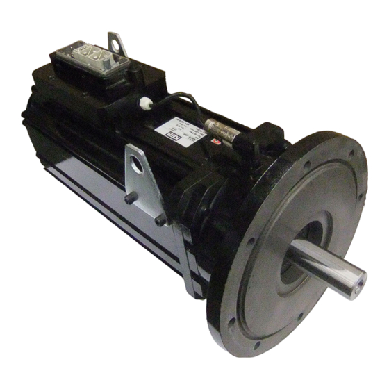
PrODUCT DESCrIPTION 2.4 General speed-torque characteristic Definition View Stall torque (n=0) max. torque Rated torque Rated speed S1-105K max. speed DC link voltage Figure 1: general speed-torque characteristic 2.5 Construction and definition 2.5.1 Drive end and direction of rotation Drive end of the motor View In DIN EN 60034-7, the two ends of a motor are defined as follows:... -
Page 21: Winding And Insulation System
PrODUCT DESCrIPTION 2.5.2 Winding and insulation system The insulation materials we use ensure insulation class 155 (F) to EN 60034. Therefore, the winding temperature may be max. 105 K at a coolant temperature of +50°C. The insulation system of the motors is designed such that they can be connected to an inverter with a maximum DC link voltage U = 840 V DC (constant 690 V DC). -
Page 22: Speed And Shaft Position Measuring System
PrODUCT DESCrIPTION ATTENTION Avoid voltage peaks when switching off! If the excitation current of the holding brake is switched off on the DC side, a voltage peak occurs which can be higher than 1000 V. It is caused by the inductance of the holding brake. A varistor should be connected in parallel to the coil to prevent this voltage peak. -
Page 23: Temperature Monitoring
PrODUCT DESCrIPTION 2.5.5 Temperature monitoring KTY84 sensors are installed as standard in the NDE winding head to protect the motor against thermal overload when the temperature change is slow (temperature change in minutes or hours). ATTENTION max. 30 VDC at temperature sensor! The maximum operating voltage of the temperature sensors must not exceed 30 VDC. -
Page 25: Technical Data
TECHNICAL DATA 3 Technical Data 3.1 Product features of servo motors for pitch systems Material numbers 7606910-40xx, 7607613-40xx Type IM B5 (IM V1, IM V3) Degree of protection IP 65 (only if the drive is mounted to a gear box !) Motor type permanent magnet synchronous servo motor Magnetic material... -
Page 26: Test Flange For Thermal Determinations
TECHNICAL DATA 3.2.1 Test flange for thermal determinations The rated power (rated torque) applies for continuous operation (duty type S1) at ambi- ent temperature of 50°C and site altitude of up to 1,000 m above sea level. It is deter- mined by using defined aluminium test flanges (see table opposite). -
Page 27: Degree Of Protection Of Servo Motors
TECHNICAL DATA 3.3 Degree of protection of servo motors See table below for the respective sealing in face of power transmission elements (transmissions etc.). Degree Shaft sealing User information protection The effect to moisture in the shaft and flange area must be kept to a minimum. No liquid IP 65 may remain in the D end shield, if the motor is mounted with the "shaft end upward"... -
Page 28: Technical Data For Servo Motor 7606910-40Xx
TECHNICAL DATA 3.4 Technical data for servo motor 7606910-40xx for inverter rated voltage 400 to 480 V AC Motor type 7606910-40xx Standstill values Stall torque [Nm] 83.0 Current at stall torque 42.2 Nominal rating Rated torque [Nm] 60.0 Rated current 30.7 Rated power [kW]... -
Page 29: Dimensions Of The Servo Motor 7606910-40Xx
TECHNICAL DATA 3.4.1 Dimensions of the servo motor 7606910-40xx +0,2 1x o-ring 79,8 -0,6 237x4 DIN 6885/1 - A - 10x8x70 28,5 DIN 332/2 - D Figure 4: Dimensions of the servo motor 7606910-40xx... -
Page 30: Shaft End For The Servo Motor 7606910-40Xx
TECHNICAL DATA 3.4.2 Shaft end for the servo motor 7606910-40xx The motor has a shaft end with a keyway to DIN 6885 Part 1. Use suitable devices for mounting and pulling off driving elements. Support the device at the D(AS) shaft end. Use suitable tool! Do not expose the motor to any impacts or blows. -
Page 31: Torque / Speed Characteristic Of The Servo Motor 7606910-40Xx
TECHNICAL DATA 3.4.3 Torque / speed characteristic of the servo motor 7606910-40xx 1000 1500 2000 [rpm] 1 Maximum DC link voltage 226V 2 Maximum DC link voltage 283V Figure 6: Torque / speed characteristic of the servo motor 7606910-40xx... -
Page 32: Technical Data For The Servo Motor 7607613-40Xx
TECHNICAL DATA 3.5 Technical data for the servo motor 7607613-40xx for inverter rated voltage 400 to 480 V AC Motor type 7607613-40xx Standstill values Stall torque [Nm] Current at stall torque 56.5 Nominal rating Rated torque [Nm] Rated current 43.7 Rated power [kW] 22.7... -
Page 33: Dimensions Of The Servo Motor 7607613-40Xx
TECHNICAL DATA 3.5.1 Dimensions of the servo motor 7607613-40xx 0.04 A 643.5 Ø 34 24.5 SPLINE DIN 5480 - 45x2x21x9g 350± 0.3 N°8-HOLES *1 corrosion protection 100µm (Tectyl-506 EH) Figure 7: Dimensions of the servo motor 7607613-40xx... -
Page 34: Shaft End For Servo Motor 7607613-40Xx
TECHNICAL DATA 3.5.2 Shaft end for servo motor 7607613-40xx The motor has a toothed shaft according to DIN 5480-45x2x21x9g. Use suitable devices for mounting and pulling off driving elements. Support the device at the D(AS) shaft end. Use suitable tool! Do not expose the motor to any impacts or blows. -
Page 35: Torque / Speed Characteristic Of The Servo Motor 7607613-40Xx
TECHNICAL DATA 3.5.3 Torque / speed characteristic of the servo motor 7607613-40xx 1000 1500 2000 2500 [rpm] Maximum DC link voltage 200V Maximum DC link voltage 565V Figure 9: Torque / speed characteristic of the servo motor 7607613-40xx... -
Page 37: Connection
CONNECTION 4 Connection The connection must be carried out in such a way that a permanently safe, elec- trical connection is maintained. In the case of improper execution of the work the type of protection IP65 is no longer warranted. If connector systems are used, then the type of protection IP65 is only achieved with correctly wired and firmly tightened mating connector. -
Page 38: Motor Connection Servo Motor 7606910-40Xx
CONNECTION 4.1.1 Motor connection servo motor 7606910-40xx Description View Connection Signal View of the motor con- nection Figure 11: Terminal assignment of the motor connection... -
Page 39: Encoder Connection Servo Motor 7606910-40Xx
CONNECTION 4.1.2 Encoder connection servo motor 7606910-40xx WArNING Adjustment of the measuring system The measuring system of synchronous motors must be adjusted to the respective inverter. Any mis-adjustment may lead to uncontrolled motor response or complete failure of the motor. In order to avoid any risk, the motor must be put into operation only in no-load operation, without connection to the system. -
Page 40: Connection Servo Motor 7607613-40Xx
CONNECTION 4.2 Connection servo motor 7607613-40xx Description View Overview of the connec- tions Figure 14: Connection servo motor 7607613-40xx... -
Page 41: Motor Connection Servo Motor 7607613-40Xx
CONNECTION 4.2.1 Motor connection servo motor 7607613-40xx Description View Connection Signal View of the motor con- nection Figure 15: Terminal assignment of the motor connection... -
Page 42: Encoder Connection Servo Motor 7607613-40Xx
CONNECTION 4.2.2 Encoder connection servo motor 7607613-40xx WArNING Adjustment of the measuring system The measuring system of synchronous motors must be adjusted to the respective inverter. Any mis-adjustment may lead to uncontrolled motor response or complete failure of the motor. In order to avoid any risk, the motor must be put into operation only in no-load operation, without connection to the system. -
Page 43: Operation Of The Servo Motor
OPErATION Of THE SErVO MOTOr 5 Operation of the Servo Motor 5.1 Preparations Before initial operation and after major inspections, check the complete plant both from a mechanical and electrical point of view. Examine that • the installation and the operating conditions comply with the specified name plate data. • the motor is properly installed and aligned. •... -
Page 44: Operation
OPErATION Of THE SErVO MOTOr 5.3 Operation In case of changes as compared to the normal operation, e.g. increased temperature, noises, oscillations, find out the cause. In case of doubt switch off the motor ! 5.4 Maintenance and repair Careful and regular maintenance and inspections are required to recognise and remedy troubles in good times, before they lead to major damage. CAUTION repairs Repairs may only be carried out by the manufacturer or an authorised... - Page 45 OPErATION Of THE SErVO MOTOr Since the operating conditions of the motors differ considerably, only general main- tenance intervals to ensure trouble-free operation can be specified. They need to be adapted to the local conditions such as the actual level of contamination, numbers of starts, load, etc.
-
Page 46: Certification
The servo motors meets the requirements of the Low-Voltage Directive EN 60034. An appropriate declaration of conformity is available if necessary via our internetportal. 6.2 further information and documentation Supplementary manuals and instructions for downloading can be found under "https://www.keb.de/de/service/downloads". General manuals • EMC and safety instructions Instructions for construction and development •... -
Page 47: Revision History
rEVISION HISTOrY 7 revision History Version Date Description 2014-11 Recreation of the manual 2015-02 Revision of the IP degree of protection 2015-04 Connection sockets adapted 2017-03 Inclusion of motor size 13, new CI... - Page 48 NOTES...
- Page 49 Tel: +55 16 31161294 E-Mail: roberto.arias@keb.de Room 1709, 415 Missy 2000 725 Su Seo Dong Gangnam Gu 135- 757 Seoul Republic of Korea Tel: +82 2 6253 6771 Fax: +82 2 6253 6770 E-Mail: vb.korea@keb.de Société Française KEB SASU france Z.I.
Need help?
Do you have a question about the 7608000-4001 and is the answer not in the manual?
Questions and answers