
Related Manuals for Gefa DG1


Summary of Contents for Gefa DG1
- Page 1 ARMATURENTECHNIK Original instructions Germaniastraße 28 • D-44379 Dortmund Tel.: +49 (0)231 / 61 00 9-0 • Fax: +49 (0)231 / 61 00 9-80 Internet: www.gefa.com • E-Mail: gefa@gefa.com Version 0 • DocID 104070923...
-
Page 2: Table Of Contents
Table of contents 1 Imprint ................................ 4 2 Safety instruction ............................ 5 2.1 Used information and warning signs ...................... 5 2.2 Intended Use............................ 6 2.3 User................................ 6 2.4 Improper use ............................ 6 2.5 Due diligence of the operator ........................ 6 2.6 Product safety ............................ - Page 3 9.13 Materials DN8-50 full bore / DN15-65 reduced bore................ 32 9.14 Materials DN65-100 full bore / DN80-150 reduced bore................ 33 9.15 Pressure-temperature diagram DN8-100.................... 34 9.15.1 Pressure-temperature diagram DN8-25.................. 34 9.15.2 Pressure-temperature diagram DN32-50.................. 35 9.15.3 Pressure-temperature diagram DN65-100.................. 36 10 How to proceed in case of malfunctions ....................
-
Page 4: Imprint
These operating instructions must be available to all users at all times. GEFA Processtechnik GmbH is not liable for unauthorized changes of the device or for improper use. -
Page 5: Safety Instruction
If contradictory identifications occur, speak with the responsible authority. All PPE (personal protective equipment) must be provided by the user of the valve. 5 / 39 Version 0 • DocID 104070923 Internet: www.gefa.com • E-Mail: gefa@gefa.com... -
Page 6: Intended Use
Data, diagrams, applications described and only in connection with the components, which are recommended by GEFA Processtechnik GmbH, ap- proved and mentioned in this documentation. The faultless and safe operation of the device requires proper transport, proper storage and installation as well as careful operation and maintenance. -
Page 7: Product Safety
2.6 Product safety The valves of GEFA Processtechnik GmbH correspond to the state of the art and the prescribed safety rules, but nervertheless hazards can occur in connection with valves. The valve may only be operated in proper condi- tion, in the intended area and under consideration of all associated documentation. Any change to the valve may only be made after approval by the manufacturer. -
Page 8: Scope Of Supply
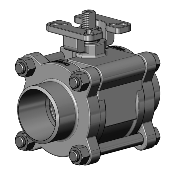
Flat hexagon nut 1.1.8 Safety cap 1.1.9 Locking clip End cap Hexagon screw Hexagon nut Hand lever Hand lever Cylinder screw Cylinder screw Hexagon screw Washer Hexagon nut 8 / 39 Version 0 • DocID104070923 Internet: www.gefa.com • E-Mail: gefa@gefa.com... -
Page 9: Exploded View Drawing Dn65-100
1.1.7 Centering ring 1.1.8 Packing gland 1.1.9 Hexagon screw End cap Hexagon screw Hexagon nut Hand lever T-piece Stop plate Pipe Cylinder screw Cylinder screw Hexagon screw 9 / 39 Version 0 • DocID 104070923 Internet: www.gefa.com • E-Mail: gefa@gefa.com... -
Page 10: Transport And Storage
For valves that are delivered without actuation, the shut-off element is not secured against adjustment. It must be transported in such a way that it can not be opened from the closed position by external influences (eg vibration). 10 / 39 Version 0 • DocID104070923 Internet: www.gefa.com • E-Mail: gefa@gefa.com... -
Page 11: Assembly And Commissioning
For operating temperatures up to max. 160°C, actuators can be mounted directly. For higher tem- peratures, a mounting kit between actuator and valve should serve as thermal insulation. 11 / 39 Version 0 • DocID 104070923 Internet: www.gefa.com • E-Mail: gefa@gefa.com... -
Page 12: Installation Conditions
The flow direction and installation position of the ball valve can be freely selected. For ball valves with pressure relief bore, the flow direction is marked on the ball valve. 12 / 39 Version 0 • DocID104070923 Internet: www.gefa.com • E-Mail: gefa@gefa.com... -
Page 13: Initial Operation
DN (F) 8/10 DN (R) Stuffing Gland Gland Spindle nut DIN439 Applicable torque [Nm] Tightening torque with graphite packing [Nm] (F) = full bore (R) = reduced bore 13 / 39 Version 0 • DocID 104070923 Internet: www.gefa.com • E-Mail: gefa@gefa.com... -
Page 14: Mounting Instructions
Avoid all foreign particles on the sealing surfaces. > Do not operate the valve in the cavitation area. The throttling and control range in an intermediate position is not permissible. 14 / 39 Version 0 • DocID104070923 Internet: www.gefa.com • E-Mail: gefa@gefa.com... -
Page 15: Operation
Valves that regularly remain in one position must be operated at regular intervals to ensure their mobility. The valve may only be operated by trained persons who know the operating instructions, understand them and can work in accordance with. 15 / 39 Version 0 • DocID 104070923 Internet: www.gefa.com • E-Mail: gefa@gefa.com... -
Page 16: Maintenance And Repair
The valves of GEFA Processtechnik GmbH are as far as possible maintenance-free. However, for operational safety reasons, all valves should nevertheless be checked regularly, for example by assessing the external con- dition and their accessories. -
Page 17: Tightening/Replacing The Stuffing Box Packing
Clean the parts, especially the sealing surfaces. > Replace the necessary components. Reassembly is performed in the reverse order of the disassembly process. Spindle tightening torques are listed in Chapter 5.3 Initial commissioning. 17 / 39 Version 0 • DocID 104070923 Internet: www.gefa.com • E-Mail: gefa@gefa.com... -
Page 18: Replacing The Seat
Switch the ball to the “CLOSED” position and then tighten the body screws (1.3). Body screws tightening torques are listed in Chapter 5.3 Initial commissioning. > Perform test shifting over the full shifting path. > ATTENTION: Risk of injury from the rotating ball. 18 / 39 Version 0 • DocID104070923 Internet: www.gefa.com • E-Mail: gefa@gefa.com... -
Page 19: Decommissioning And Disposal
The opening of pneumatic actuators or pneumatic cylinders, which are equipped with a closing or opening spring, is associated with increased risk. It is essential to follow the maintenance and re- pair instructions. Maintenance and repair instructions can be found on www.gefa.com or request them directly from us. -
Page 20: Technical Data And Materials
11/4“ 31.8 4xM10 11/2“ 42.8 11/2“ 4xM10 2“ 54.2 2“ 50.7 4xM12 Weight including hand lever *R2 Octagon ** Pipe thread DIN 2999-Rp, ISO 228/1-G Subject to changes 20 / 39 Version 0 • DocID104070923 Internet: www.gefa.com • E-Mail: gefa@gefa.com... -
Page 21: Dimension Sheet Dn65-100 - Full Bore - Threaded End And Short Butt Weld End
4“ 4“ 4xM16 27.2 Weight including hand lever * Option: Length increased by 100 mm for insulation ** Pipe thread DIN 2999-Rp, ISO 228/1-G Subject to changes 21 / 39 Version 0 • DocID 104070923 Internet: www.gefa.com • E-Mail: gefa@gefa.com... -
Page 22: Dimension Sheet Dn15-65 - Reduced Bore - Threaded End And Short Butt Weld End
4xM8 11/2“ 11/2“ 31.8 4xM10 2“ 2“ 4xM10 21/2“ 21/2“ 50.7 4xM12 Weight including hand lever *R2 Octagon ** Pipe thread DIN 2999-Rp, ISO 228/1-G Subject to changes 22 / 39 Version 0 • DocID104070923 Internet: www.gefa.com • E-Mail: gefa@gefa.com... -
Page 23: Dimension Sheet Dn80-150 - Reduced Bore - Threaded End And Short Butt Weld End
4xM14 12.0 4“ 6xM14 18.8 5“ 6xM16 28.1 6“ 6xM16 28.7 Weight including hand lever * Option: Length increased by 100 mm for insulation Subject to changes 23 / 39 Version 0 • DocID 104070923 Internet: www.gefa.com • E-Mail: gefa@gefa.com... -
Page 24: Dimension Sheet Dn8-100 - Full And Red. Bore - Threaded End And Short Butt Weld End With Ap Series Actuator
AP(M)2 AP(M)3 AP(M)2 AP(M)3 AP(M)2 AP(M)3 AP(M)3 AP(M)3.5 AP(M)4 AP(M)3.5 AP(M)4 AP(M)4.5 AP(M)4 AP(M)4.5 AP(M)5 AP(M)4 125/150 AP(M)4.5 AP(M)5 *Dimension G only for APM series Subject to changes 24 / 39 Version 0 • DocID104070923 Internet: www.gefa.com • E-Mail: gefa@gefa.com... -
Page 25: Dimension Sheet Dn8-50 - Full Bore - Long Butt Weld End
4xM6 1/2“ 4xM8 3/4“ 19.5 30.5 4xM8 1“ 4xM8 11/4“ 34.5 31.8 4xM10 11/2“ 40.5 4xM10 2“ 50.5 50.7 4xM12 Weight including hand lever Subject to changes 25 / 39 Version 0 • DocID 104070923 Internet: www.gefa.com • E-Mail: gefa@gefa.com... -
Page 26: Dimension Sheet Dn8-50 - Full Bore - Orbital End
33.7 11/4“ 29.5 31.8 4xM10 42.4 11/2“ 37.0 4xM10 48.3 2“ 47.0 50.7 4xM12 60.3 Weight including hand lever Material of butt weld end: 1.4409 Subject to changes 26 / 39 Version 0 • DocID104070923 Internet: www.gefa.com • E-Mail: gefa@gefa.com... -
Page 27: Dimension Sheet Dn65-100 - Full Bore - Orbital End
4“ 97.5 6xM16 114.3 29.0 Weight including hand lever Material of butt weld end: 1.4409 * Option: Length increased by 100 mm for insulation Subject to changes 27 / 39 Version 0 • DocID 104070923 Internet: www.gefa.com • E-Mail: gefa@gefa.com... -
Page 28: Dimension Sheet Dn10-50 - Full Bore - V-Flange Pn10-40
10 - 40 43.1 4x18 2“ 10 - 16 54.5 4x18 50.7 10.2 2“ 25 - 40 54.5 4x18 50.7 10.8 Weight including hand lever Subject to changes 28 / 39 Version 0 • DocID104070923 Internet: www.gefa.com • E-Mail: gefa@gefa.com... -
Page 29: Dimension Sheet Dn65-100 - Full Bore - V-Flange Pn10-40
8x18 27.8 4“ 107.1 8x22 39.9 Weight including hand lever * Option: Length increased by 100 mm for insulation ** Option: Flange connection 8x18 Subject to changes 29 / 39 Version 0 • DocID 104070923 Internet: www.gefa.com • E-Mail: gefa@gefa.com... -
Page 30: Dimension Sheet Dn8-50 Full / Dn15-65 Reduced Bore With T-Hand Lever
8/10 DN (R) 0.26 0.26 0.26 0.51 0.51 0.51 0.51 (F) = full bore (R) = reduced bore *Weight of hand lever Material: Stainless steel Subject to changes 30 / 39 Version 0 • DocID104070923 Internet: www.gefa.com • E-Mail: gefa@gefa.com... -
Page 31: Dimension Sheet, Actuator Connection Din 3337 / Iso 5211
(R) = reduced bore Square adapter DIN 3337 / ISO 5211: F07 / F10 DN65 (F) – DN100 (F) DN80 (R) - DN150 (R) Subject to changes 31 / 39 Version 0 • DocID 104070923 Internet: www.gefa.com • E-Mail: gefa@gefa.com... -
Page 32: Materials Dn8-50 Full Bore / Dn15-65 Reduced Bore
9.13 Materials DN8-50 full bore / DN15-65 reduced bore Position Designation Material DG1 6666 ** T… DG1 W 6666**T… DG1 6644 **T… DG1 6969 ** T… Ball valve Center section 1.1.1 Body 1.4408 1.4408 1.4408 1.4529 1.1.2 Ball 1.4408 1.4408 1.4408... -
Page 33: Materials Dn65-100 Full Bore / Dn80-150 Reduced Bore
9.14 Materials DN65-100 full bore / DN80-150 reduced bore Position Designation Material DG1 6666 ** T… DG1 W 6666**T… DG1 6644 **T… DG1 6969 ** T… Ball valve Center section 1.1.1 Body 1.4408 1.4408 1.4408 1.4529 1.1.2 Ball 1.4408 1.4408 1.4408... -
Page 34: Pressure-Temperature Diagram Dn8-100
PTFE / carbon seat UHMWPE seat The diagrams refer to ball valves with full bore. For ball valves with reduced bore, select a smaller nominal size. Subject to changes 34 / 39 Version 0 • DocID104070923 Internet: www.gefa.com • E-Mail: gefa@gefa.com... -
Page 35: Pressure-Temperature Diagram Dn32-50
PTFE / carbon seat UHMWPE seat The diagrams refer to ball valves with full bore. For ball valves with reduced bore, select a smaller nominal size. Subject to changes 35 / 39 Version 0 • DocID 104070923 Internet: www.gefa.com • E-Mail: gefa@gefa.com... -
Page 36: Pressure-Temperature Diagram Dn65-100
PTFE / carbon seat UHMWPE seat The diagrams refer to ball valves with full bore. For ball valves with reduced bore, select a smaller nominal size. Subject to changes 36 / 39 Version 0 • DocID104070923 Internet: www.gefa.com • E-Mail: gefa@gefa.com... -
Page 37: How To Proceed In Case Of Malfunctions
When returning the product to the manufacturer, enclose the safety data sheet of the media. Furthermore, if ne- cessary, it must be stated which safety measures have to be observed when handling the returned product. 37 / 39 Version 0 • DocID 104070923 Internet: www.gefa.com • E-Mail: gefa@gefa.com... -
Page 38: Annex
Remove attached actuators before removing the valve or secure them against unauthorized use and accidental operation. 38 / 39 Version 0 • DocID104070923 Internet: www.gefa.com • E-Mail: gefa@gefa.com... -
Page 39: Structure Of The Hand Lever
> For the stop (open or closed position), insert the cylinder screw (2.5) and tighten it with the nut (2.6). 39 / 39 Version 0 • DocID 104070923 Internet: www.gefa.com • E-Mail: gefa@gefa.com...
Need help?
Do you have a question about the DG1 and is the answer not in the manual?
Questions and answers