Sign In
Upload
Manuals
Brands
Gefa Manuals
Control Unit
DG1
Gefa DG1 Manuals
Manuals and User Guides for Gefa DG1. We have
1
Gefa DG1 manual available for free PDF download: Original Instructions Manual
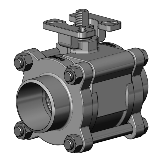
Gefa DG1 Original Instructions Manual (39 pages)
Brand:
Gefa
| Category:
Control Unit
| Size: 15 MB
Table of Contents
Table of Contents
2
Imprint
4
Safety Instruction
5
Used Information and Warning Signs
5
Intended Use
6
User
6
Improper Use
6
Due Diligence of the Operator
6
Product Safety
7
Product-Specific Dangers
7
Outflowing Media
7
Failure of Actuator Operating Power
7
Mounting of Actuators
7
Scope of Supply
8
Exploded View Drawing DN8-50
8
Components
8
Exploded View Drawing DN65-100
9
Components
9
Transport and Storage
10
Assembly and Commissioning
11
Installation Conditions
12
Installation Position
12
Initial Operation
13
Mounting Instructions
14
Impermissible Operation
14
Operation
15
Maintenance and Repair
16
Maintenance
16
Tightening/Replacing the Stuffing Box Packing
17
Replacing the Seat
18
Decommissioning and Disposal
19
Decommissioning
19
Removing of the Valve
19
Disposal
19
Technical Data and Materials
20
Dimension Sheet DN8-50 - Full Bore - Threaded End and Butt Weld End, Short
20
Dimension Sheet DN65-100 - Full Bore - Threaded End and Short Butt Weld End
21
Dimension Sheet DN15-65 - Reduced Bore - Threaded End and Short Butt Weld End
22
Dimension Sheet DN80-150 - Reduced Bore - Threaded End and Short Butt Weld End
23
Dimension Sheet DN8-100 - Full and Red. Bore - Threaded End and Short Butt Weld End with AP Series Actuator
24
Dimension Sheet DN8-50 - Full Bore - Long Butt Weld End
25
Dimension Sheet DN8-50 - Full Bore - Orbital End
26
Dimension Sheet DN65-100 - Full Bore - Orbital End
27
Dimension Sheet DN10-50 - Full Bore - V-Flange PN10-40
28
Dimension Sheet DN65-100 - Full Bore - V-Flange PN10-40
29
Dimension Sheet DN8-50 Full / DN15-65 Reduced Bore with T-Hand Lever
30
Dimension Sheet, Actuator Connection DIN 3337 / ISO 5211
31
Materials DN8-50 Full Bore / DN15-65 Reduced Bore
32
Materials DN65-100 Full Bore / DN80-150 Reduced Bore
33
Pressure-Temperature Diagram DN8-100
34
Pressure-Temperature Diagram DN8-25
34
Pressure-Temperature Diagram DN32-50
35
Pressure-Temperature Diagram DN65-100
36
How to Proceed in Case of Malfunctions
37
Annex
38
Structure of Control Elements
38
Structure of the Hand Lever
39
Advertisement
Advertisement
Related Products
Gefa AT 200F series
Gefa Domino AT 100 Series
Gefa Domino AT 150 Series
Gefa Domino AT 200 Series
Gefa Domino AT 300 Series
Gefa Domino AT 400 Series
Gefa Domino AT 600 Series
Gefa HG1
Gefa HG7
Gefa Categories
Control Unit
Controller
More Gefa Manuals
Login
Sign In
OR
Sign in with Facebook
Sign in with Google
Upload manual
Upload from disk
Upload from URL