Table of Contents
Advertisement
Quick Links
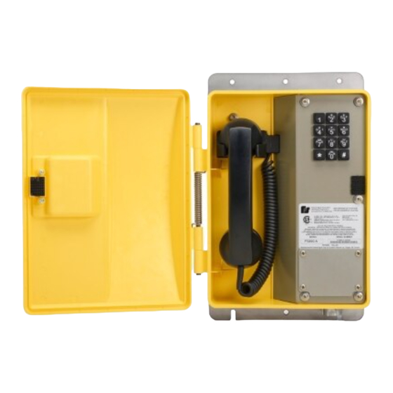
FT200C-V
Weather Resistant VoIP Hazardous Location
Telephone
25500869 Rev A0 1123
Limited Warranty: This product's limited warranty can be
found at www.fedsig.com/SSG-Warranty.
SAFETY MESSAGES TO INSTALLERS AND USERS
The equipment is not intended for repair by the user. Repair of this equipment shall be carried out by the manufacturer
or manufacturer's authorised agent.
It is the responsibility of the end user to take suitable precautions to prevent exposure to aggressive chemicals that
may attack metals or the polymeric materials used in the construction of this equipment. Specific details of vulnerable
materials shall be provided in the instructions.
•
Read and understand instructions before installing or operating equipment.
•
Do not install this device near any heat sources such as radiators, heat registers, stoves, or other apparatus
(including amplifiers) that produce heat.
•
Only use attachments and accessories specified by the manufacturer.
•
Refer all servicing to qualified service personnel.
•
Prior to installation, consult local building and electrical code requirements.
•
WARNING: ELECTRICAL HAZARD — This product should be installed by a licensed electrician according to all
electrical and building codes.
•
WARNING: HAZARDOUS AREA — Before opening the enclosure, ensure that the area is safe and that the power
conductors are not live. When replacing the faceplate, ensure that the wires or other foreign objects are not trapped
between the edges. Anything the prevents the base and the faceplate from being in direct contact nullifies the
hazardous area rating of the telephone.
•
WARNING: DISLOCATION HAZARD — To prevent injury, this apparatus must be securely attached to the floor or
wall in accordance with the installation instructions.
•
Suitable for use in class i, division 2, groups a, b, c and d hazardous locations or nonhazardous locations only.
•
WARNING: EXPLOSION HAZARD — Do not disconnect equipment while the circuit is live or unless the area is
known to be free of ignitable concentrations.
•
WARNING: EXPLOSION HAZARD — Substitution of components may impair suitability for class I, division 2
hazardous locations.
•
WARNING: CHEMICAL HAZARD — Exposure to some chemicals may degrade the sealing properties of materials
used in the sealed relay device.
Failure to follow all safety precautions and instructions may result in property damage, serious injury, or death to you or
others.
:
Advertisement
Table of Contents

Related Manuals for Federal Signal Corporation FT200C-V


Summary of Contents for Federal Signal Corporation FT200C-V
- Page 1 FT200C-V Weather Resistant VoIP Hazardous Location Telephone 25500869 Rev A0 1123 Limited Warranty: This product’s limited warranty can be found at www.fedsig.com/SSG-Warranty. SAFETY MESSAGES TO INSTALLERS AND USERS The equipment is not intended for repair by the user. Repair of this equipment shall be carried out by the manufacturer or manufacturer’s authorised agent.
- Page 2 Table 1 Specifications Electrical Performance Ringer Output >80 dB Microphone Noise reducing electret Receiver Hearing aid compatible Category Ethernet I/F 10/100 MBPS Protocol SIP RFC 3261 compatible Power Input - Method #1 802.3 AF compliant PoE switch or power injector - Method #2 24 Vdc at 1A power adapter CODECS Supported...
- Page 3 GENERAL: The Federal Signal FT200C-V weatherproof, hazardous location telephone is designed to provide safe, reliable communication in areas prone to high humidity, chemical vapors, dust, and physical abuse. The telephone is compatible with most SIP-based IP PBX servers that comply with SIP RFC 3261. Users can remotely monitor and program settings through a web browser to configure the telephone on their network.
-
Page 4: Supported Protocols
The Voice-over-IP (VoIP) FT200C-V Telephone is a Power-over-Ethernet (PoE 802.3af) and Voice-over-IP (VoIP) two-way communications device that easily connects into existing local area networks (LANs) with a single cable connection. Figure 1 illustrates how the FT200C-V Telephone can be installed as part of a VoIP phone system. Figure 1 Typical VoIP Installation... - Page 5 Figure 2 Features Figure 3 Dimensions SHOCK HAZARD: If using an auxiliary power supply, ensure that it is unplugged during installation to avoid an accidental shock or circuit damage. NOTES: • Follow all appropriate electrical codes and use only approved electrical fittings for the installation •...
- Page 6 • Choose a wall location that is free of obstructions and permits space for conduit runs. • Ensure that mounting can support 7 lb (3.2 kg) and any additional foreseeable load. To install the telephone: Separate the faceplate from the housing. Use the template provided or the enclosure itself to locate and drill holes for mounting screws.
-
Page 7: Operation
Call to and from another telephone, preferably a VoIP device, to test the unit. Operation The FT200C-V telephone may be set up for either keypad dialing or auto-dialing. If the telephone is configured for keypad, dialing operation is identical to most other single-line telephones. - Page 8 Connecting a Device to an Auxiliary Relay The FT200C-VoIP Telephone incorporates a one on-board relay located on the PCBA, which enables users to control a low current external relay or device. An external relay can control a ringer, strobe light, door lock, or any other apparatus. The on-board relay is protected by a 1 A, non-replaceable fuse.
-
Page 9: Network Connectivity And Data Rate
Network Connectivity and Data Rate When you plug in the Ethernet cable or power supply, the square, green Link light above the Ethernet port indicates that the network connection has been established. (See Figure 8.) The Link light changes color to confirm the auto-negotiated baud rate: •... -
Page 10: Announcing The Ip Address
Announcing the IP Address To announce a telephone’s current IP address: Press and release the RESET switch (SW1). Do not hold more than five seconds. The telephone announces that it is restoring the factory default settings. NOTE: The telephone uses DHCP to obtain the new IP address (DHCP-assigned address or default to 10.10.10.10 if a DHCP server is not present). -
Page 11: Cleaning The Telephone
Ringer Replacement To replace a ringer: Disconnect the ringer wiring from the terminal block on the PCBA. Remove the screws that hold the ringer to the housing. Install the new ringer and gasket. Reconnect the ringer wiring to the terminal block. Main Circuit Board Replacement To replace the circuit board: Label any wiring attached to the circuit board. -
Page 12: Maintenance And Service
Maintenance and Service Technical Assistance: Contact our Technical Support Team at +1 708-587-3587 or signalsupport@fedsig.com. Repair Service: A return authorization is required. Contact your Authorized Distributor or Federal Signal Customer Support. Defective products under warranty will be repaired or replaced at Federal Signal’s discretion. Product Returns: Returns require authorization from Federal Signal.
Need help?
Do you have a question about the FT200C-V and is the answer not in the manual?
Questions and answers