Advertisement
Quick Links
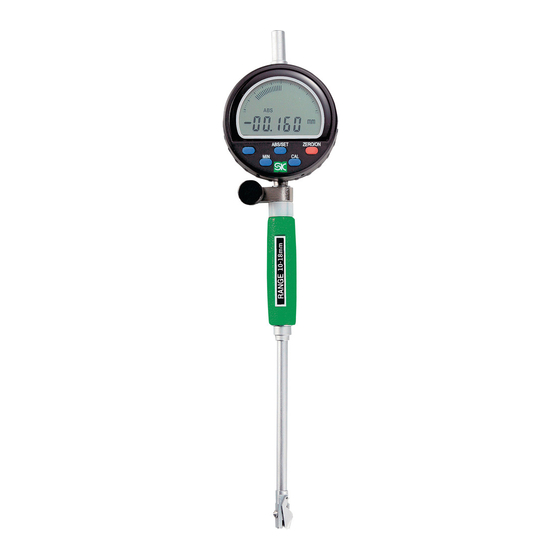
DIGITAL BORE GAUGE
Thank you for purchasing the Digital Bore Gauge.
Please read this manual thoroughly before use for proper operation.
■ PART IDENTIFICATION
Gauge
( Digital Indicator )
LCD Display
[ ABS/SET ]
※2
Button
ABS
※1
[ ZERO/ON ]
ABS/SET
ZERO/ON
MIN
CAL
Button
[ MIN ] Button
[ CAL ] Button
Clamp
※1:Not Used
Screw
※2:"0.01" indicates the resolution of
Cap
the display's digital bar graph.
The bar graph display will
change with each 0.01mm
Handle
change in the measured value.
Shaft
Extension
Rod
Measurement
Head
Probe
Tip
Probe
【WCDI-10D】
Extension
Tip
Rod
Measurement
Guide
Head
【WCDI-18D】
【Accessories】
(WCDI-10D) (WCDI-18D)
(WCDI-10D) (WCDI-18D)
Spanner
※Spanners shown in drawing
Extension Rod
above vary slightly in
Washer 0.5mm
(WCDI-18D only)
appearance, but function will
be same.
■ INSERTING・REPLACING BATTERY
Pull out the case from the two
side edges to remove. Insert
Battery
(CR2032)
battery with
+
side facing
(
)
down.
NOTICE
Battery
Case
Use only CR2032 type lithium
button cell.
■AUTO OFF DELAY
①Press and hold the [ ZERO/ON ] Button to turn power OFF.
②Press and hold [ ABS/SET ] and [ ZERO/ON ] Buttons at the
same time.
③When 「-----」 is displayed, ❶release the [ ZERO/ON ] Button,
❷then release the [ ABS/SET ] Button in that sequence.
④The Auto Off Delay time will be displayed. Press [ ABS/SET ]
to change.
※Each press of the [ ABS/SET ] Button will change the delay
by 1/2 hr. ( 30 min. ) from 0 to 6 hr.
⑤Press [ ZERO/ON ] when done and display will return to the
measurement screen.
※Once set, the delay time is saved even when power is OFF.
Instruction Manual
Model No. : WCDI-10D/ WCDI-18D
■ SPECIFICATIONS
*Including supplied Digital Gauge
※Not including quantization error ( ±1 count )
WCDI -10D
WCDI -18D
Model No.
(mm)
Measuring Range
6 -10
(mm)
Resolution
0 . 0 0 2
*
※
(μm)
Wide range accuracy
12
*
※
(μm)
Adjacent error
5
*
※
(μm)
Repeatability
3
(mm)
Single Stroke Range
0 .7
0 〜 6.0
(h r)
Auto Off Delay
( g )
Weight
2 6 5
ACCESSORIES
●Extension Rods
WCDI-10D ・・・・ 6・6.5・7・7.5・8・8.5・9・9.5・10mm (9 pieces)
WCDI-18D ・・・・ 10・11・12・13・14・15・16・17・18mm (9 pieces)
●Washer ・・・・・・・ 0.5mm (WCDI-18D only)
●Spanner ・・・・・・ 1x
●Battery ・・・・・・・ CR2032 Lithium button cell, 1x (for test)
NOTICE
●This is a precision instrument, handle with care.
●Do not disassemble or modify.
●Keep instrument away from water and oil.
●Use only with supplied Extension Rods and Washer.
●Keep instrument away from direct sunlight and high temperatures
such as in a car, or near a stove or heat source.
●After use, remove any dirt or cutting chips and apply rust
preventative oil to Extension Rod and Washer. When not in use
store in supplied storage case.
●This product is for measuring inside diameter; use only as directed.
Improper use may cause accident or injury.
●Avoid using in high electric fields, such as near fluorescent lights or
switching power supplies. Electrical interference may cause
incorrect readings.
■ ASSEMBLY
①Loosen the Clamp Screw and insert
the Digital Indicator into the gauge
body. Tighten the Clamp Screw to
secure.
※After attaching, press the [ ZERO/ON ]
Button on the Digital Indicator to turn on
power. Confirm that the displayed
reading changes by gently squeezing the
Clamp
measurement head. If necessary, adjust
Screw
the depth that the Digital Indicator is
inserted into the gauge body.
② Select the Extension Rod, washer ( WCDI-18Donly ) for the desired
measurement range.
Ex.) WCDI-10D set to 8.5mm
1. Use the Spanner to loosen the
Nut at the bottom of
Measurement Head.
Ex. Rod
8.5mm
2. Install the Extension Rod and
tighten.
Spanner
Ex.) WCDI-18D set to 14.5mm
Attach the Extension Rod,
Washer to the bottom of the
Measurement Head and tighten
+
with the Spanner.
Ex. Rod
Washer
14mm
0.5mm
■ MEASUREMENT
For accurate measurements, follow the procedure described below.
<
>
combined
①In cross section perpendicular to the axis of the bore, as shown in Figure 1, position the gauge along diameter ⓐ. This is the
maximum distance, and at this point the Indicator will read the maximum value. The Guide will automatically position the Measurement
Head to diameter ⓐ when inserted.
※WCDI-10D does not have a guide on the Measurement Head so please manually position at this maximum value.
②In cross section parallel to the axis of the bore through diameter ⓐ, position the indicator to minimize the distance ⓑ. ( Figure 2 )
In this position the Indicator will read the minimum value. This position must be manually determined by pivoting the Gauge as shown
in Figure 3 while watching the Indicator to find the minimum value.
10 -18
a
0 . 0 0 2
12
5
3
0 . 9
(Fig.1)
3 0 0
■ OPERATION
①Before use, please make sure the Measurement Head components are not loose and tighten if necessary.
②Clean the Measurement Head and the ID of a Ring Gauge Standard using parts cleaner or cleaning solution.
③Press the [ ZERO/ON ] Button to turn on power. ※ A long press to the [ ZERO/ON ] Button will turn power off.
ABSOLUTE MODE ( ABS )
①Turn on power. If the "
②Adjust the "SET" value of the Bore Gauge to match the ID of the Ring Gauge Standard. Press and hold the [ ABS/SET ] Button until
"SET" blinks on the display.
③Continue holding the [ ABS/SET ] Button and the display character to the left will blink. Use a short press of the [ ABS/SET ] Button to
change the value, and a long press to change the character being modified. Repeat this process to enter the dimension of the Ring
Gauge Standard on the LCD display. ( Figure 4 )
④When the value is entered the flashing position will return to "SET". A short
press of the [ ABS/SET ] Button to turn off the flashing.
⑤Insert the Measurement Head into the Ring Gauge Standard and press the
[ MIN ] Button to put the Indicator into minimum-mode. Slowly pivot the
gauge ( Figure 3 ) to display the minimum value.
⑥Remove the gauge from the Ring Gauge and press the [ CAL ] Button until
"OK" is displayed.
Preparation for measurement is now complete.
⑦Put the gauge into the workpiece to be measured, and pivot the gauge
slowly. ( Figure 3 ) The LCD will display the measured value. ( Figure 5 )
※Press the [ ON/ZERO ] Button momentarily to reset display in preparation
to measure the next workpiece.
ABS/SET
ZERO/ON
MIN
CAL
COMPARATIVE MEASUREMENTS
①Turn on power. If "
" or "
press the [ MIN ] Button to turn off. If "ABS" is displayed press the
[ ABS/SET ] Button to turn off.
②Insert the Measurement Head into the Ring Gauge Standard and press
[ MIN ] Button to put the Indicator into minimum-mode. Slowly pivot the
gauge ( Figure 3 ) to display the minimum value.
③Remove the gauge from the Ring Gauge and press the [ CAL ] Button until
"OK" is displayed.
Preparation for measurement is now complete.
④Put the gauge into the workpiece to be measured, and pivot the gauge
slowly. ( Figure 3 ) The LCD will display the difference between the
measured workpiece and the calibration standard. ( Figure 6 )
※Press the [ ON/ZERO ] Button momentarily to reset display in preparation
Nut
to measure the next workpiece.
Spanner
■TROUBLESHOOTING
ERROR
●LCD does not display
●Displayed value is unstable
●Display is not clear
b
(Fig.2)
(Fig.3)
※Measure absolute dimension of workpiece
" or "
" symbols are displayed on the LCD, press the [ MIN ] Button to turn off.
※Difference between workpiece and reference
" symbols are displayed on the LCD,
※If problem persists, or if you have any
CORRECTIVE ACTION
questions, please contact distributor.
●Cycle power by removing and
※Please note, manufacturer is unable to
replacing battery.
respond to inquires or provide service
●Replace battery with new one.
directly. Please contact distributor.
ABS
ABS/SET
ZERO/ON
Ring Gauge
MIN
CAL
Set to match
Standard
(Fig.4)
ABS
ABS/SET
ZERO/ON
Work-
Workpiece I.D. value
piece
MIN
CAL
(Fig.5)
Work-
ABS/SET
ZERO/ON
piece
MIN
CAL
Diff. between Work-
piece and Reference
(Fig.6)
Niigata Seiki Co., Ltd.
5-3-14, Tsukanome, Sanjo, Niigata, Japan, 955-0055
Tel. : +81-256-33-5522 Fax. : +81-256-33-5518
MAIL intl.sales@niigataseiki.co.jp
URL
http://www.niigataseiki.co.jp
Advertisement

Related Manuals for Niigata seiki WCDI-10D


Summary of Contents for Niigata seiki WCDI-10D
- Page 1 Thank you for purchasing the Digital Bore Gauge. Head to diameter ⓐ when inserted. Please read this manual thoroughly before use for proper operation. ※WCDI-10D does not have a guide on the Measurement Head so please manually position at this maximum value. ■ PART IDENTIFICATION ■ SPECIFICATIONS ②In cross section parallel to the axis of the bore through diameter ⓐ, position the indicator to minimize the distance ⓑ.
- Page 2 振り、最小値を表示させてください。 ●本製品は内径測定用機器です。用途以外のご使用は、事故やけが ⑥測定部をマスタとなるリングゲージから抜き、CALボタンを長押しし 【付属品】 の原因となりますので絶対におやめください。 マスタとなる ABS/SET ZERO/ON てください。『OK』が表示されます。 数値を合わせる リングゲージ ●インバータ式蛍光灯などの電界が発生する場所でのご使用は避け これで測定の準備が完了しました。 (図4) てください。LCD表示部の数値が誤作動を起こす原因となります。 (WCDI-10D) (WCDI-18D) (WCDI-10D) (WCDI-18D) スパナ ⑦ワークに測定子を入れ、 (図3) のようにシリンダゲージをゆっくりと振っ 換えロッ ド ■本体の組み付け て、 測定してください。 LCD表示部に、 測定値が表示されます。 (図5) ※スパナの形状は上図と若干 ※次のワークを測定する際は、 ZERO/ONボタンを一度押してください。 ワッシャ0.5mm 異なる場合がありますが、 ①取付ねじをゆるめ、指示器を本体に差 (WCDI-18Dのみ) 使用上問題ありません。 し込みます。...