Advertisement
Quick Links
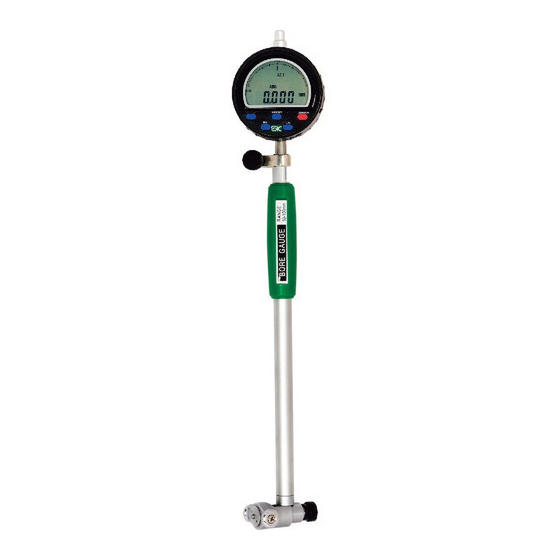
DIGITAL BORE GAUGE
Thank you for purchasing the Digital Bore Gauge.
Please read this manual thoroughly before use for proper operation.
■PART IDENTIFICATION
Gauge
LCD Display
( Digital Indicator )
[ ABS/SET ]
Button
※2
ABS
※1
[ ZERO/ON ]
ABS/SET
ZERO/ON
MIN
CAL
Button
[ MIN ] Button
[ CAL ] Button
[ CAL ] Button
Clamp
※1:Not Used
Screw
※2:"0.01" indicates the
Cap
resolution of the display's
digital bar graph. The bar
graph display will change
with each 0.01mm change
in the measured value.
Handle
【Accessories】
0.5mm 1mm 2mm 3mm
Washers
Shaft
Extension Rod
Mounting
Nut
Sub Rod 55mm
(WCDI-160D only)
Extension
Rod
Probe Tip
Measurement
Guide
Head
■ INSERTING・REPLACING BATTERY
Pull out the case from
the two side edges to
Battery
(CR2032)
remove. Insert battery
with
(
+
)
side facing
down.
Battery
Case
NOTICE
Use only CR2032 type
lithium button cell.
■ AUTO OFF DELAY
①Press and hold the [ ZERO/ON ] Button to turn
power OFF.
②Press and hold [ ABS/SET ] and [ ZERO/ON ]
Buttons at the same time.
③When 「-----」 is displayed, ❶release the
[ ZERO/ON ] Button, ❷then release the
[ ABS/SET ] Button in that sequence.
④The Auto Off Delay time will be displayed. Press
[ ABS/SET ] to change.
※Each press of the [ ABS/SET ] Button will change
the delay by 1/2 hr. ( 30 min. ) from 0 to 6 hr.
⑤Press [ ZERO/ON ] when done and display will
return to the measurement screen.
※Once set, the delay time is saved even when power
is OFF.
Instruction Manual
Model No. : WCDI-50D/WCDI-100D/WCDI-160D
■ SPECIFICATIONS
* :Including supplied Digital Gauge
※Not including quantization error ( ±1 count )
Model No.
WCDI -50D
WCDI -100D
(mm)
Measuring Range
3 5- 5 0
5 0 - 10 0
(mm)
Resolution
0.002
0.002
*
※
(μm)
Wide range accuracy
15
18
*
(μm)
※
Adjacent error
5
6
*
(μm)
※
Repeatability
3
3
(mm)
Single Stroke Range
1. 2
1. 6
0 〜 6 . 0
(h r)
Auto Off Delay
( g )
Weight
4 5 0
475
ACCESSORIES
●Extension Rods
WCDI-50D・・・・35・40・45・50mm (4pieces)
WCDI-100D・・・50・55・60・65・ 70・ 75・80・85・90・95・ 100mm (11 pieces)
WCDI-160D・・・50・55・60・65・ 70・ 75・80・85・90・95・ 100・ 105mm (12 pieces)
●Sub Rod・・・・・55mm×1x(WCDI-160D only)
●Washer・・・・・0.5・1・2・3mm ( 1 each size )
●Battery・・・・・・CR2032Lithium button cell, 1x ( for test )
NOTICE
●This is a precision instrument, handle with care.
●Do not disassemble or modify.
●Keep instrument away from water and oil.
● Use only with supplied Extension Rods and Washer.
●Keep instrument away from direct sunlight and high temperatures such as in
a car, or near a stove or heat source.
● After use, remove any dirt or cutting chips and apply rust preventative oil to
Extension Rod and Washer. When not in use store in supplied storage case.
●This product is for measuring inside diameter; use only as directed. Improper
use may cause accident or injury.
●Avoid using in high electric fields, such as near fluorescent lights or switching
power supplies. Electrical interference may cause incorrect readings.
■ ASSEMBLY
①Loosen the Clamp Screw and insert the Digital
Indicator into the gauge body. Tighten the Clamp
Screw to secure.
※After attaching, press the [ ZERO/ON ] Button on the
Digital Indicator to turn on power. Confirm that the
displayed reading changes by gently squeezing the
measurement head. If necessary, adjust the depth
that the Digital Indicator is inserted into the gauge
body.
② Select the combination of Sub Rod ( WCD-160
only ) Extension Rod and Washers for the
dimension you want to measure.
Remove the Rod Adj. Nut put on the desired Sub Rod, Rod, and Washers,
and secure with the Extension Rod Mounting Nut.
※Please select combination with fewest number of Washers.
【Examples】
To
Measure:
6 0
mm
Ex. Rod Nut
Ex. Rod 60mm
To
Measure:
62.5
mm
+
Ex. Rod
Washer
60mm
2mm
To
Measure:
118
mm
+
+
Ex. Rod
Washer
Sub Rod
60mm
3mm
55mm
■ MEASUREMENT
<
>
For accurate measurements, follow the procedure described below.
combined
①In cross section perpendicular to the axis of the bore, as shown in Figure 1, position the gauge along diameter ⓐ. This is the
maximum distance, and at this point the Indicator will read the maximum value. The Measurement Head will automatically move to
diameter ⓐ when inserted.
②In cross section parallel to the axis of the bore through diameter ⓐ, position the indicator to minimize the distance ⓑ. ( Figure 2 )
In this position the Indicator will read the minimum value. This position must be manually determined by pivoting the Gauge as
shown in Figure 3 while watching the Indicator to find the minimum value.
WCDI -160D
5 0 - 16 0
a
0.002
18
6
3
1. 6
(Fig.1)
5 7 0
■ OPERATION
①Before use, please make sure the Measurement Head components are not loose and tighten if necessary.
②Clean the Measurement Head and the ID of a Ring Gauge Standard using parts cleaner or cleaning solution.
③Press the [ ZERO/ON ] Button to turn on power. ※ A long press to the [ ZERO/ON ] Button will turn power off.
ABSOLUTE MODE ( ABS )
①Turn on power. If the "
②Adjust the "SET" value of the Bore Gauge to match the ID of the Ring Gauge Standard. Press and hold the [ ABS/SET ] Button until
"SET" blinks on the display.
③Continue holding the [ ABS/SET ] Button and the display character to the left will blink. Use a short press of the [ ABS/SET ] Button to
change the value, and a long press to change the character being modified. Repeat this process to enter the dimension of the Ring
Gauge Standard on the LCD display. ( Figure 4 )
④When the value is entered the flashing position will return to "SET". A short
press of the [ ABS/SET ] Button to turn off the flashing.
⑤Insert the Measurement Head into the Ring Gauge Standard and press the
[ MIN ] Button to put the Indicator into minimum-mode. Slowly pivot the
gauge ( Figure 3 ) to display the minimum value.
⑥Remove the gauge from the Ring Gauge and press the [ CAL ] Button until
"OK" is displayed.
Preparation for measurement is now complete.
⑦Put the gauge into the workpiece to be measured, and pivot the gauge
slowly. ( Figure 3 ) The LCD will display the measured value. ( Figure 5 )
※Press the [ ON/ZERO ] Button momentarily to reset display in preparation
ABS/SET
ZERO/ON
MIN
CAL
to measure the next workpiece.
COMPARATIVE MEASUREMENTS
①Turn on power. If "
press the [ MIN ] Button to turn off. If "ABS" is displayed press the
[ ABS/SET ] Button to turn off.
②Insert the Measurement Head into the Ring Gauge Standard and press
Clamp
Screw
[ MIN ] Button to put the Indicator into minimum-mode. Slowly pivot the
gauge ( Figure 3 ) to display the minimum value.
③Remove the gauge from the Ring Gauge and press the [ CAL ] Button until
"OK" is displayed.
Preparation for measurement is now complete.
④Put the gauge into the workpiece to be measured, and pivot the gauge
slowly. ( Figure 3 ) The LCD will display the difference between the
measured workpiece and the calibration standard. ( Figure 6 )
※Press the [ ON/ZERO ] Button momentarily to reset display in preparation
to measure the next workpiece.
■ TROUBLESHOOTING
+
Washer
0.5mm
ERROR
●LCD does not display
●Displayed value is unstable
●Display is not clear
b
(Fig. 2)
(Fig. 3)
※Measure absolute dimension of workpiece
" or "
" symbols are displayed on the LCD, press the [ MIN ] Button to turn off.
※Difference between workpiece and reference
" or "
" symbols are displayed on the LCD,
※If problem persists, or if you have any
CORRECTIVE ACTION
questions, please contact distributor.
●Cycle power by removing and
※Please note, manufacturer is unable to
replacing battery.
respond to inquires or provide service
●Replace battery with new one.
directly. Please contact distributor.
ABS
ABS/SET
ZERO/ON
Ring Gauge
Standard
MIN
CAL
Set to match
(Fig. 4)
ABS
Work-
ABS/SET
ZERO/ON
piece
Workpiece I.D. value
MIN
CAL
(Fig. 5)
Work-
ABS/SET
ZERO/ON
piece
MIN
CAL
Diff. between Work-
piece and Reference
(Fig.6)
Niigata Seiki Co., Ltd.
5-3-14, Tsukanome, Sanjo, Niigata, Japan, 955-0055
Tel. : +81-256-33-5522 Fax. : +81-256-33-5518
MAIL intl.sales@niigataseiki.co.jp
URL
http://www.niigataseiki.co.jp
Advertisement

Related Manuals for Niigata seiki WCDI-50D


Summary of Contents for Niigata seiki WCDI-50D
- Page 1 ■ MEASUREMENT Instruction Manual DIGITAL BORE GAUGE Model No. : WCDI-50D/WCDI-100D/WCDI-160D < > For accurate measurements, follow the procedure described below. combined ①In cross section perpendicular to the axis of the bore, as shown in Figure 1, position the gauge along diameter ⓐ. This is the Thank you for purchasing the Digital Bore Gauge.
- Page 2 質 量 45 0 キャップ (g) 周のバーグラフの単位です。 付属品 ①ご使用の前に、測定部と外筒の間がゆるんでいないか確認し、ゆるんでいたら締め付けてください。 測定値に0.01mmの変動が あ っ た 場 合 そ れ に 応 じ て 、 ●換えロッド ②測定子を含めた測定部と、基準リングゲージの内径をパーツクリーナーなどの洗浄液で洗浄します。 バーグラフも1本増減します。 WCDI-50D・・・・35・40・45・50mm(計4本) にぎり WCDI-100D・・・50・55・60・65・70・75・80・85・90・95・100mm ③ZERO/ONボタンを押して、電源をONにしてください。※電源をOFFにする時は、ZERO/ONボタンを長押ししてください。 (計11本) WCDI-160D・・・50・55・60・65・70・75・80・85・90・95・100・105mm (計12本) 【付属品】 ●サブロッド・・・・・55mm×1本 (WCDI-160Dのみ) 絶対測定 (ABS) ※ワークのサイズを絶対値で表示します。 ●ワッシャ・・・・・・・0.5・1・2・3mm (各1枚) 0.5mm 1mm 2mm 3mm ●電 池・・・・・・・・・CR2032 (コイン型リチウム電池:...