Advertisement
Quick Links
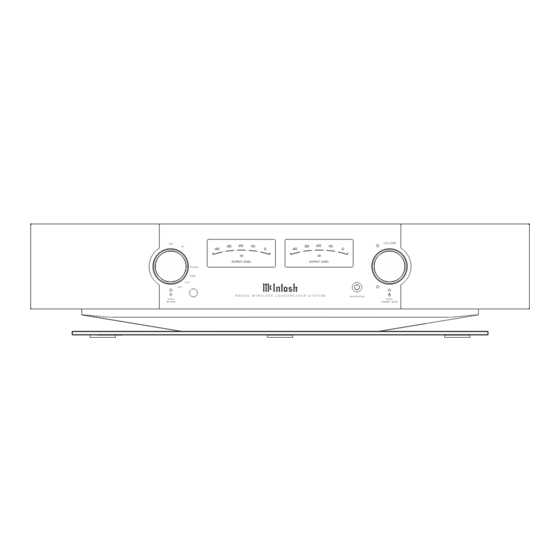
MC312
RS250
NET
-20
-30
BT
-40
OUTPUT LEVEL
PHONO
HDMI
AUX
OPT
R S 2 5 0 W I R E L E S S L O U D S P E A K E R S Y S T E M
PUSH
BT PAIR
POWER AMPLIFIER
WIRELESS LOUDSPEAKER SYSTEM
SERIAL NO. AGW1001 And Above
SERIAL NO. AKJ1001
-20
-10
-30
-10
0
-40
0
dB
dB
OUTPUT LEVEL
HEADPHONE
And Above
VOLUME
PUSH
POWER / MUTE
SERVICE MANUAL
SERVICE MANUAL
CONTENTS
CONTENTS
Performance Specifications ........................................................ 2
Performance Specifications & Notes ..............................................2
Notes......................................................................................... 2
Rear Panel ............................................................................................2
Rear Panel ................................................................................. 2
Section Locations ...............................................................................3
Block Diagram ................................................................................. 4-5
Section Location ........................................................................ 3
Interconnection Diagram .................................................................6
Block Diagram ........................................................................... 4
Main Schematic & PCB ................................................................ 7-20
Interconnect Diagram and Parts List ...................................... 5 - 6
Amplifier Schematic & PCB ...................................................... 21-23
Main Schematic, PCB and Parts List .................................... 7 - 11
Headphone Out Jack Schematic & PCB .......................................24
Rectifier Schematic, PCB and Parts List ....................................12
Audio Schematic & PCB ............................................................ 25-26
Capacitor, PCB and Parts List .............................................13 - 14
FPP Converter Schematic & PCB ...................................................27
Left and Right Converter Schematic & PCB ................................28
Left Input, Schematics, PCB and Parts List ..........................15 - 16
Display Schematic & PCB .......................................................... 29-30
Right Input, Schematic, PCB and Parts List ......................... 17 - 18
Control Switch Left Schematic & PCB ..........................................31
Heatsink Schematic, PCB and Parts List .............................19 - 22
Control Switch Right Schematic & PCB .......................................32
Left Terminal Schematic, PCB and Parts List ......................23 - 24
Logo Board Schematic & PCB ........................................................33
Right Terminal Schematic, PCB and Parts List ................... 25 - 26
Power Supply Schematic & PCB ....................................................34
Display Left Meter/Right Meter Light ..................................27 -28
Wireless Network Board Schematic & PCB ........................... 35-36
Packing ...............................................................................................37
Repacking Instruction .............................................................. 29
Advertisement

Related Manuals for McIntosh RS250


Summary of Contents for McIntosh RS250
- Page 1 MC312 RS250 POWER AMPLIFIER WIRELESS LOUDSPEAKER SYSTEM SERIAL NO. AGW1001 And Above SERIAL NO. AKJ1001 And Above SERVICE MANUAL SERVICE MANUAL CONTENTS CONTENTS Performance Specifications ............2 Performance Specifications & Notes ..........2 Notes..................2 Rear Panel ....................2 Rear Panel ................. 2 Section Locations ................3...
- Page 2 RS250 NO SERVICEABLE PARTS PERFORMANCE SPECIFICATIONS Technical Specifications Technical Specifications Continued Technical Specifications Continued NOTES Power Output Sub out Frequencies Dimensions 650W - 400W Tweeter/Mids, 250W Woofers 20Hz to 500Hz Width 24 13/16 inches (62.99cm) 1. Unless otherwise noted, all voltages indicated on the...
- Page 3 NO SERVICEABLE PARTS RS250 SECTION LOCATIONS AMP PCB AUDIO PCB MAIN PSU PCB RIGHT CONVERTER NETWORK CONVERTER LEFT CONVERTER DISPLAY Additional Service Information VOLUME Item Description Quantity Part Number 2” Driver 03621900 Woofer 310659SP HEADPHONE Tweeter 310660SP Control Knob 310662SP...
- Page 4 RS250 NO SERVICEABLE PARTS BLOCK DIAGRAM (1 of 2) headphone Ph ono MM Ph ono Pre -am p LC FILTER Switch 3.5MM TWEETER TP A3255 SPD IF LEFT 2XBTL SPD IF SPDIF LC FILTER MID-FREQ SiI9612 eARC e ARC SiI9437...
- Page 5 NO SERVICEABLE PARTS RS250 BLOCK DIAGRAM (2 of 2) DC/DC 12V unit +5VP Stream810module TPS54202 700 W ? Stream810module EN PM OS 3V3IO Stream810module 51V unit 36V unit +3.3VS +3.3V PM OS +3.3VC 13 mA CODEC DC/DC 3A TPS54335 +3.3VD...
- Page 6 RS250 NO SERVICEABLE PARTS INTERCONNECT...
- Page 7 NO SERVICEABLE PARTS RS250 MAIN 320780SP SCH - Original Board (Option A) 1 of 14 Support 2A U1300 C1300 +5VP FB1300 L 1300 FB1301 BOOT +5VP 15uH C1301 C1302 100nF/50V WiFi 500m A R1301 R1302 100R C1308 R1303 100k/1% 13K3/1%...
- Page 8 RS250 NO SERVICEABLE PARTS MAIN 320780SP SCH - (Option B) w/direct converter board 2 of 14 Support 2A U1300 C1300 +5VP FB1300 L 1300 FB1301 BOOT +5VP 15uH C1301 C1302 100nF/50V WiFi 500m A R1302 R1301 100R R1303 100k/1% C1308...
- Page 9 NO SERVICEABLE PARTS RS250 MAIN 320780SP SCH - 3 of 14...
- Page 10 RS250 NO SERVICEABLE PARTS MAIN 320780SP SCH - 4 of 14 MAIN 320780SP SCH - 5 of 14...
- Page 11 NO SERVICEABLE PARTS RS250 MAIN 320780SP SCH - 6 of 14...
- Page 12 RS250 NO SERVICEABLE PARTS MAIN 320780SP SCH - 7 of 14...
- Page 13 NO SERVICEABLE PARTS RS250 MAIN 320780SP SCH - 8 of 14...
- Page 14 RS250 NO SERVICEABLE PARTS MAIN 320780SP SCH - 9 of 14 OPTION - B...
- Page 15 NO SERVICEABLE PARTS RS250 MAIN 320780SP SCH - 10 of 14...
- Page 16 RS250 NO SERVICEABLE PARTS MAIN 320780SP SCH - 11 of 14...
- Page 17 NO SERVICEABLE PARTS RS250 MAIN 320780SP SCH - 12 of 14...
- Page 18 RS250 NO SERVICEABLE PARTS MAIN 320780SP SCH - 13 of 14...
- Page 19 NO SERVICEABLE PARTS RS250 MAIN 320780SP SCH - 14 of 14...
- Page 20 RS250 NO SERVICEABLE PARTS MAIN 320780SP PCB 1 of 2 MAIN 320780SP PCB 2 of 2...
- Page 21 NO SERVICEABLE PARTS RS250 AMPLIFIER SCH 320776SP 1 of 2...
- Page 22 RS250 NO SERVICEABLE PARTS AMPLIFIER SCH 320776SP 2 of 2...
- Page 23 NO SERVICEABLE PARTS RS250 AMPLIFIER PCB 320776SP 1 of 2 AMPLIFIER PCB 320776SP 2 of 2...
- Page 24 RS250 NO SERVICEABLE PARTS HEADPHONE OUT JACK SCH 320777SP HEADPHONE OUT JACK PCB 320777SP...
- Page 25 NO SERVICEABLE PARTS RS250 AUDIO SCH 320779SP...
- Page 26 RS250 NO SERVICEABLE PARTS AUDIO PCB 1 of 2 320779SP AUDIO PCB 2 of 2 320779SP...
- Page 27 NO SERVICEABLE PARTS RS250 FPP CONVERTER SCH 320781 FPP CONVERTER PCB 320781...
- Page 28 RS250 NO SERVICEABLE PARTS LEFT AND RIGHT CONVERTER SCH 320782SP LEFT AND RIGHT CONVERTER PCB ASSEMBLY 320782SP...
- Page 29 NO SERVICEABLE PARTS RS250 DISPLAY SCH 320783SP...
- Page 30 RS250 NO SERVICEABLE PARTS DISPLAY SCH PCB 320783SP...
- Page 31 NO SERVICEABLE PARTS RS250 CONTROL SWITCH LEFT SCH 320384SP CONTROL SWITCH LEFT PCB 320784SP...
- Page 32 RS250 NO SERVICEABLE PARTS CONTROL SWITCH RIGHT SCH 320785SP CONTROL SWITCH RIGHT PCB 320785SP...
- Page 33 NO SERVICEABLE PARTS RS250 LOGO BOARD SCH 320786SP LOGO BOARD PCB 320786SP...
- Page 34 RS250 NO SERVICEABLE PARTS POWER SUPPLY 320787SP PCB...
- Page 35 NO SERVICEABLE PARTS RS250 WIRELESS NETWORK BOARD PCB 1 of 2 320778SP...
- Page 36 RS250 NO SERVICEABLE PARTS WIRELESS NETWORK BOARD PCB 2 of 2 320778SP...
- Page 37 Re-packing the RS250 When shipping the RS250, it is highly recommended that the unit be packed as it was originally shipped to avoid damage. Failure to properly pack the unit will likely result in damage. If you need any of the packing material, you can contact McIntosh Customer Service.
- Page 38 (ARC) OPTICAL LEVEL ADJUST RS250 REAR VIEW 1 11/25/20 RS250 REAR VIEW 2 7/25/22 JM The continuous improvement of its products is the policy of McIntosh Laboratory Incorporated, who reserve the right to improve design without notice. Because of the constant upgrading of McIntosh products’...
Need help?
Do you have a question about the RS250 and is the answer not in the manual?
Questions and answers