Table of Contents
Advertisement
Quick Links
Instructions
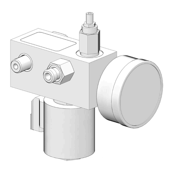
Direct Mount Vent Valve
®
for G3
Used to reduce system pressure and allow injector to reset. For professional use only.
Not approved for use in explosive atmospheres or hazardous (classified) locations.
Model 2001401
Right Side Mount, 115 VAC, BSPP
700 psi (4.8 MPa, 48.3 bar) Maximum Working Pressure
Important Safety Instructions
Read all warnings and instructions in this
manual and your G3 pump manual
before using the equipment. Be familiar
with the proper control and usage of the
equipment. Save these instructions.
Related Manuals
Find English manuals and any available translations at
www.graco.com.
English
Manual
Description
Number
332291
G3 Standard Automatic Lubrication Pump
332298
G3 Pro Automatic Lubrication Pump
332305
G3 Max Automatic Lubrication Pump
Pumps
3A9475A
EN
Advertisement
Table of Contents

Related Manuals for Graco 2001401


Summary of Contents for Graco 2001401
- Page 1 Used to reduce system pressure and allow injector to reset. For professional use only. Not approved for use in explosive atmospheres or hazardous (classified) locations. Model 2001401 Right Side Mount, 115 VAC, BSPP 700 psi (4.8 MPa, 48.3 bar) Maximum Working Pressure...
-
Page 2: Safety Symbols
Safety Symbols Safety Symbols The following safety symbols appear throughout this manual and on warning labels. Read the table below to understand what each symbol means. Symbol Meaning Electric Shock Hazard Moving Parts Hazard Skin Injection Hazard Skin Injection Hazard Splash Hazard Follow Pressure Relief Procedure Ground Equipment... -
Page 3: Installation
Installation Installation WARNING 3. Verify that the two o-rings (8, 9) are correctly installed on the bolt (7) (F . 1). ELECTRIC SHOCK HAZARD • This equipment must be grounded. Improper grounding, setup, or usage of the system can cause electric shock. •... - Page 4 Installation 6. Grease the o-ring (6) and install in the block 9. Connect the cable connector (13) to the solenoid opening (1a) (F . 3). valve (a) (F . 5). 7. Verify that the o-ring (5) is on the bolt (4) (F .
-
Page 5: Pressure Relief Valve
• The pressure relief valve included in this kit can only be used with a Graco G3 pump. It is not intended for use with any other products. • Factory set to 200 psi (1.4 MPa, 13.8 bar) adjust- able to 750 psi (5.17 MPa, 51.7 bar). -
Page 6: Operation
Operation Operation Recycle and Disposal Pressure Relief Procedure End of Product Life Follow the Pressure Relief Procedure whenever At the end of the product’s useful life, dismantle and you see this symbol. recycle it in a responsible manner. WARNING • Perform the Pressure Relief Procedure, page 6. - Page 7 Parts Parts Part No. 2001401 Ref. Part Description Manifold 126039 Valve, cartridge, 115 AC, DIN 2001394 Valve, Pressure Relief Bolt, Vent Valve Mount, BSPP O-ring, 908 O-ring, 015 Bolt, Vent Valve O-ring, 012 O-ring, 014 112567 Pressure Gauge ▲ Replacement safety labels, tags, and cards are available at no cost.
-
Page 8: Technical Specifications
Technical Specifications Technical Specifications DIRECT MOUNT VENT VALVE FOR G3 PUMPS Metric Maximum working pressure 700 psi 4.8 MPa, 48.3 bar Pressure Relief Valve Factory Set Pressure 200 psi 1.37 MPa, 13.7 bar adjustable to 750 psi + 10 percent 5.17 MPa, 51.7 bar + 10 percent Reset Pressure 80 percent of pressure... -
Page 9: California Proposition
Technical Specifications California Proposition 65 CALIFORNIA RESIDENTS WARNING: Cancer and reproductive harm – www.P65warnings.ca.gov. 3A9475A... -
Page 10: Graco Standard Warranty
With the exception of any special, extended, or limited warranty published by Graco, Graco will, for a period of twelve months from the date of sale, repair or replace any part of the equipment determined by Graco to be defective.
Need help?
Do you have a question about the 2001401 and is the answer not in the manual?
Questions and answers