Table of Contents
Advertisement
Quick Links
THANK YOU
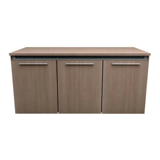
Thank you for purchasing the C5 Series credenza rack. Please read these instructions thoroughly
before installing or assembling this product.
PRODUCT FEATURES
•
Built-in thermostatically controlled cooling.
•
Heavy duty frame ships separate to allow for equipment integration before finished surfaces
are attached.
•
Available in a variety of color options.
•
There are 14 rackspaces per bay.
•
Factory installed casters.
Instruction Sheet
C5 Series
Credenza Rack
I-00661
Rev K
Advertisement
Table of Contents

Related Manuals for LEGRAND MIDDLE ATLANTIC C5 Series


Summary of Contents for LEGRAND MIDDLE ATLANTIC C5 Series
- Page 1 Instruction Sheet C5 Series Credenza Rack THANK YOU Thank you for purchasing the C5 Series credenza rack. Please read these instructions thoroughly before installing or assembling this product. PRODUCT FEATURES • Built-in thermostatically controlled cooling. • Heavy duty frame ships separate to allow for equipment integration before finished surfaces are attached.
-
Page 2: Table Of Contents
TABLE OF CONTENTS Important Safety Instructions......................3 - 5 Weight Ratings............................5 Supplied Components and Hardware....................6 Required Tools............................6 Introduction............................7 Understanding Blower Operation.......................8 Viewing The Blue LED Power Indicator on Blower................8 Installing Rear Anti-Tip Feet (C5-FF2-X Models Only)...............9 Lowering Front and Rear Anti-Tip Feet....................9 Installing Vent.............................9 Installing Side Panels........................10 Installing Top Surface........................10... -
Page 3: Important Safety Instructions
IMPORTANT SAFETY INSTRUCTIONS - EN • Read these instructions. • Heed all warnings. • Clean only with dry cloth. • Keep these instructions. • Follow all instructions. • Only use attachments/accessories specified by the manufacturer. DANGER HAZARDOUS VOLTAGE: The lightning flash with the arrowhead symbol, within an equilateral triangle is intended to alert the user to the presence of uninsulated dangerous voltage within the product’s enclosure that may be of sufficient magnitude to constitute a risk of electric shock to persons. - Page 4 IMPORTANT SAFETY INSTRUCTIONS - EN (CONTINUED) When using an electrical furnishing, basic precautions should always be followed, including the following: • For institutional use. • Read and follow all instructions before using. • Refer all servicing to qualified service personnel. Servicing is required when the apparatus has been damaged in any way, such as power-supply cord or plug is damaged, liquid has been spilled or objects have fallen into the apparatus, the apparatus has been exposed to rain or moisture, does not operate normally, or has been dropped.
-
Page 5: Weight Ratings
INSTRUCTIONS IMPORTANTES SUR LA SÉCURITÉ - FR (A CONTINUÉ) Pour éviter une condition instable, placer des composants plus lourds dans le bas de l'armoire. Lorsque plus d'un ATTENTION composant sera placé dans l'armoire, commencez en bas de l'armoire, placent l'équipement sur le point le plus bas disponible, distribuant uniformément le poids (verticalement) dans l l'armoire. -
Page 6: Supplied Components And Hardware
(2x) Phillips Screw Forming Screws Rear Anti-Tip Feet NOTE: • To order more hardware, contact support at av.support@legrand.com or (866) 977-3901. • Additional hardware is included that may not be required for your installation. REQUIRED TOOLS • Phillips Screwdriver WARNING: Use tools with caution and follow all necessary safety •... -
Page 7: Introduction
INTRODUCTION NOTE: • Please take the time to carefully unpack and inspect all components and gather all corresponding instruction sheets. • Instruction sheets may also be accessed at www.legrandav.com. • Maintenance and care information is provided in Care and Cleaning of Products (I-00788) and Unpacking and Handling Precautions (I-00787) for your convenience. -
Page 8: Understanding Blower Operation
UNDERSTANDING BLOWER OPERATION FOR 1-BAY MODEL ONLY: Only one master blower is pre-installed on top of credenza frame. (FIGURE A) FOR 2-BAY AND 3-BAY MODELS ONLY: A master blower and remote blower(s) are pre-installed on top of credenza frame. Only the remote blower has an interconnect lead coming out of the rear (and is powered by the master). -
Page 9: Installing Rear Anti-Tip Feet (C5-Ff2-X Models Only)
INSTALLING REAR ANTI-TIP FEET (C5-FF22-X MODELS ONLY) FOR 1-BAY MODELS: Rear anti-tip feet are pre-installed. FOR 2- AND 3-BAY MODELS: Install rear anti-tip feet before assembling your credenza. 5/16” deep socket and (8x) 10-32 x ⅜” thread forming screws (H) to install both rear anti-tip •... -
Page 10: Installing Side Panels
INSTALLING SIDE PANELS FOR C5-FF27-X and C5-FF31-X MODELS ONLY: If installing a C5MM monitor mount kit, install stabilizing feet and monitor mount support brackets prior to attaching wood-side panels and doors to frame. For more information, refer to the C5 Large Format Display Mount System Instruction Sheet (I-00749) at www.legrandav.com. -
Page 11: Installing Doors
INSTALLING DOORS FOR ALL MODELS: Follow the step listed below to install the outer doors to the wood side panels. NOTE: If using an electric drill, verify the torque is on the lightest setting and only increase as neces- sary. •... -
Page 12: Adjusting The Door(S)
ADJUSTING THE DOOR(S) • If necessary, use a #2 Phillips screwdriver to adjust door hinges, as shown. (FIGURE L) Door in open position. FIGURE L Side Adjustment: Adjusts horizontal placement of door. Adjusts door-to-door gap. Height Adjustment: Adjusts vertical height of door. Depth Adjustment: Adjusts the space between the door and the face of the frame of credenza. -
Page 13: Installing Spring Latch
INSTALLING SPRING LATCH • Install latch using (2x) screws per spring latch (C), as shown. (FIGURE N) FOR METAL FRAME: Use 4-40 x ¼” machine screws (A) when installing spring latch (C) into frame. FOR WOOD KIT: Use #4 x ½” wood screws (B) when installing spring latch (C) into wood. FIGURE N Page 13... -
Page 14: Warranty
Unit C, Island Rd. Eden Prairie, MN, 55344, USA DK, Weert, Netherlands Reading RG2, 0RP- UK At Legrand AV Inc. we are always listening. Your comments are welcome. Legrand AV is an ISO 9001 and ISO 14001 Registered Company. Page 14...
Need help?
Do you have a question about the MIDDLE ATLANTIC C5 Series and is the answer not in the manual?
Questions and answers