
Subscribe to Our Youtube Channel
Related Manuals for Cutech 40800H


Summary of Contents for Cutech 40800H
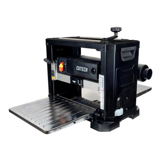
- Page 1 User Manual Read this manual before using machine to avoid serious injury and damage 40800H 2 SPEED 13” SPIRAL CUTTERHEAD PLANER For technical support, email support@cutechtools.us or call 858-886-7333 VER. 08.29.23.
-
Page 2: Table Of Contents
The drawings, illustrations, photographs, and specifications in this user manual represent your machine at time of print. However, changes may be made to your machine or this manual at any time with no obligation to CUTECH. -
Page 3: Warranty
Center for inspection. If the warranty claim is considered to be invalid due to exclusions listed above, CUTECH will at your direction dispose of or return the product. In the event you choose to have the product returned, you will be responsible for the handling and shipping cost of the return. -
Page 4: Product Specifications
PRODUCT SPECIFICATIONS Feed speed F/min 16 or 26 FPM Cutterhead speed RPM 10,000 Motor RPM 23,000+/-10% (No Load) Cutterhead diameter 2” Max planer capacity 6” x 13" Max depth of cut @ 6” 1/8” Max depth of cut @ 13” 1/16”... -
Page 5: General Safety
GENERAL SAFETY NOTE: The WARNING! CAUTION! symbols indicate a potentially hazardous situation which, if not avoided, COULD result in death or serious injury. READ THIS MANUAL completely before assembling and operating this machine. WARNING! TO AVOID serious injury, death, or damage to the machine, please read, understand, and follow, all Safety and Operating Instructions before assembling and operating this machine. - Page 6 GENERAL SAFETY (cont.) CAUTION! ALWAYS unplug the machine from the electrical receptacle when making adjustments, changing parts or performing any maintenance. AVOID ACCIDENTAL STARTING. Make sure that the power switch is in the “OFF” position before plugging in the power cord to the electrical receptacle. WARNING! AVOID a dangerous working environment.
- Page 7 GENERAL SAFETY (cont.) MAINTAIN all machines with care. ALWAYS KEEP machine clean and in good working order. KEEP all blades and tool bits sharp. NEVER leave a machine running, unattended. Turn the power switch to the OFF position. DO NOT leave the machine until it has come to a complete stop. REMOVE ALL MAINTENANCE TOOLS from the immediate area prior to turning the machine ON.
-
Page 8: Product Safety
DO NOT handle the plug or planer with wet hands. USE only accessories as described in this manual and recommended by CUTECH. 10. DO NOT pull the planer by the power cord. NEVER allow the power cord to come in contact with sharp edges, hot surfaces, oil or grease. - Page 9 PRODUCT SAFETY (cont.) 14. ENSURE that the machine sits firmly before using. If the machine wobbles or is unstable, correct the problem by attaching to a bench top prior to operation. 15. This machine is designed to process wood ONLY. WARNING! NEVER position fingers or thumbs near the infeed/ outfeed rollers or cutterhead.
-
Page 10: Grounding Instructions
GROUNDING INSTRUCTIONS WARNING! This machine MUST BE GROUNDED while in use to protect the operator from electric shock. In the event of a malfunction or breakdown, GROUNDING provides the path of least resistance for electric current and reduces the risk of electric shock. The plug MUST be plugged into a matching electrical receptacle that is properly installed and grounded in accordance with ALL local codes and ordinances. - Page 11 GROUNDING INSTRUCTIONS (cont.) Make certain the extension cord is properly sized, and in good electrical condition. Always replace a worn or damaged extension cord immediately or have it repaired by a qualified person before using it. Protect your extension cords from sharp objects, excessive heat, and damp or wet areas. MINIMUM RECOMMENDED GAUGE FOR EXTENSION CORDS (AWG) 120 VLOT OPERATION OLNY 25’...
-
Page 12: Unpacking & Inventory
If any parts are missing, do not attempt to plug in the power cord and turn “ON” the machine. The machine should only be turned “ON” after all the parts have been obtained and installed correctly. For missing parts, contact CUTECH by email support@cutechtools.us or call 858-886-7333. -
Page 13: Assembly
ASSEMBLY WARNING! MAKE CERTAIN THAT THE MACHINE IS DISCONNECTED FROM THE POWER SOURCE. ATTACHING DEPTH ADJUSTMENT HANDLE Attach the raise/lower adjustment handle to the shaft located on top of the planer and fasten in place with 1 Hex Socket Head screw. Tighten screw using supplied hex wrench. SEE FIG 1. - Page 14 ASSEMBLY (cont.) 2. To minimize sawdust accumulation on your work piece, attach either a 2-1/2 in. or a 4 in. vacuum hose to the dust port. 3. The dust port must be snapped shut completely or chips may fly out of the front of the planer.
-
Page 15: Adjustments
ADJUSTMENTS WARNING! MAKE CERTAIN THAT THE MACHINE IS DISCONNECTED FROM THE POWER SOURCE BEFORE ANY ADJUSTMENTS ARE MADE. LEVELING EXTENSION TABLES The extension tables must be level with the planer table. To check the extension tables and adjust if necessary: Lay a straight edge (A) on the planer table (C) with one end of the straight edge over the infeed table (B). - Page 16 ADJUSTMENTS (cont.) RAISING AND LOWERING HEAD ASSEMBLY The head assembly consists of the cutterhead, knives, feed rollers, cutterhead guard, and the motor. Raising and lowering of the head assembly controls the depth of cut on the planer. To adjust: To raise the head assembly (A), turn the adjusting handle (B) clockwise. SEE FIG 6. To lower the head assembly, turn the adjusting handle counterclockwise.
- Page 17 ADJUSTMENTS (cont.) ADJUSTING / REPLACING KNIVES FOR THE SPIRAL CUTTERHEAD WARNING! MAKE CERTAIN THAT THE MACHINE IS DISCONNECTED FROM THE POWER SOURCE BEFORE ANY ADJUSTMENTS ARE MADE. WARNING! ***Be VERY CAREFUL when handling the knives or cutter tips as they are EXTREMELY SHARP and can cause serious injury!!! *** This 13"...
- Page 18 ADJUSTMENTS (cont.) Lubricate the Torx screw threads with light machine oil and wipe the excess oil off the threads. Install cutter tip insert and torque the Torx screw to 48-60 lbf-in. FIG 7 NOTE: Proper cleaning of tips and cutterhead is critical to achieving a smooth finish. Dirt or dust trapped between the cutter insert and cutterhead will slightly raise the cutter insert, and make noticeable marks on your work piece the next time you plane.
-
Page 19: Operations
OPERATIONS NOTE: This operations section was designed to give instructions on the basic operations of this planer. However, it is in no way comprehensive of every planer operation. It is strongly recommended that you read books, trade magazines, or get formal training to maximize the potential of your planer while minimizing the risks. - Page 20 OPERATIONS (cont.) REPEAT CUT PRESET The REPEAT CUT preset, located on the right side of the planer, provides a simple way to preset the finished thickness of a work piece. The indicator can be set to various thicknesses. Move the lever to the desired finished thickness. Use this feature when thickness planing multiple work pieces to ensure a uniform thickness of all work pieces.
- Page 21 OPERTIONS (cont.) GETTING PREPARED It is always a good idea to use a piece of scrap wood for your first planing attempt. Also, before each use of the planer, make it a habit of checking for loose fasteners, fittings or hardware.
- Page 22 OPERTIONS (cont.) GENERAL TIPS AND GUIDELINES 1. Thickness planing always works best when at least one side of the work piece has a flat surface. If both sides of the work piece are rough, feed one face of the board through the planer until the entire surface is flat.
-
Page 23: Maintenance
MAINTENANCE WARNING! MAKE CERTAIN THAT THE MACHINE IS DISCONNECTED FROM THE POWER SOURCE BEFORE PERFORMING ANY MAINTENANCE PROCEDURES Your planer should provide you with a long time of service provided you take the time to perform the following maintenance operations. CLEANING Sawdust buildup and other debris can cause the tool to plane incorrectly. - Page 24 MAINTENANCE (cont.) BRUSH REPLACEMENT Brush life will vary depending on the load placed on the motor. The brushes should be inspected every 10-15 hours of use. To inspect or replace: Remove the brush holders, one of which is shown at (A). The other is located in the same position on the rear of the motor assembly.
-
Page 25: Troubleshooting Guide
TROUBLESHOOTING GUIDE Motor and Machine Operation PROBLEM LIIKELY CAUSE SOLUTION Snipe Dull Blades Replace or rotate tips. Readjust (depressions at Infeed or outfeed tables out of tables. Feed scrap of same end of work piece) adjustment. thickness before and after work Residue on rollers. -
Page 26: Parts
PARTS... -
Page 27: Parts List
PARTS LIST DESCRIPTION SIZE #1、#3(3)、#5、#10(2)、#142、#204 TOP COVER RETURN ROLLER #1B(4)、#1C(4)、#1D(4)、#1E(4) 1B_S RETURN ROLLER SEAT HEX SOC HD CAP SCR ELEVATION NUT UPPER FRAME LEFT SIDE PANEL RIGHT SIDE PANEL KNOB HANDLE CASE SCR HEX SOC BUT HD IDLE WHEEL IDLE WHEEL SHAFT SPINDLE HEIGHT ADJ SPINDLE HEX SOC HD SCR... - Page 28 PARTS LIST (cont.) DESCRIPTION SIZE SPECIAL WASHER #39、#39A DUST HOOD ASSY. ADAPTOR SPRING FLAT SCR SEMS S/WASH SCR SEMS W/WASH SCREW DUST CHUTE PLATE NYLOCK SCR SOC SET CUP PT SCR PAN CR CORD CLAMP SCR HEX SOC HD LOCK WASHER WASHER SCREW HEX HD...
- Page 29 PARTS LIST (cont.) DESCRIPTION SIZE SCR PN CR TYTT LOCKWASHER EXT FEED RATE LABEL C-RING SPROCKET SPROCKET CHAIN WHEEL SPRING BLOCK BEARING OUTFEED ROLLER SPRING PLATE RETAINER SCR HEX SOC CAP INFEED ROLLER #90、#102、#103(5)、#104、#105、 #106(4)、#107(2)、#108、#109、 #110、#111、#112、#114(2)、#120、 102_S GEAR BOX #121、#122、#123、#124、#125(2)、 #126、#127 SCREW SPACER...
- Page 30 PARTS LIST (cont.) DESCRIPTION SIZE SCREW HEX NUT HEX BALL BEARING WA SHER SCR HEX SOC CAP CHAIN SCR HEX SOC CAP WASHER WASHER LOGO LABEL SPEC LABEL LABEL LABEL #51、#65、#191、#195、#250~#255、 250_S MOTOR ASSY. #257~#260、#262~#278、#280~#281 BRUSH HOLDER BRUSH BRUSH CAP SWITCH...
Need help?
Do you have a question about the 40800H and is the answer not in the manual?
Questions and answers