Table of Contents

Subscribe to Our Youtube Channel
Related Manuals for Cutech 40180HB-CT


Summary of Contents for Cutech 40180HB-CT
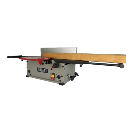
- Page 1 User Manual Read this manual before using machine to avoid serious injury and damage 40180H-CT / 40180HB-CT 40180HI-CT 8” SPIRAL CUTTERHEAD JOINTER For technical support, email support@cutechtools.us or call 858-886-733 VER. 12.01.22.
-
Page 2: Table Of Contents
The drawings, illustrations, photographs, and specifications in this user manual represent your machine at time of print. However, changes may be made to your machine or this manual at any time with no obligation to CUTECH. -
Page 3: Warranty
Center for inspection. If the warranty claim is considered to be invalid due to exclusions listed above, CUTECH will at your direction dispose of or return the product. In the event you choose to have the product returned, you will be responsible for the handling and shipping cost of the return. -
Page 4: Product Specifications
PRODUCT SPECIFICATIONS Cutterhead speed RPM 12,000 Motor RPM 19000+/-10% (No Load) Cutterhead diameter 2” Max width of cut 8” Max depth of cut 1/8” Cutter inserts qty Motor power input AC Only, 120 V, 60 Hz, 10 Amp Fence Size 4-3/8”... -
Page 5: General Safety
GENERAL SAFETY NOTE: The WARNING! CAUTION! symbols indicate a potentially hazardous situation which, if not avoided, COULD result in death or serious injury. READ THIS MANUAL completely before assembling and operating this machine. WARNING! TO AVOID serious injury, death, or damage to the machine, please read, understand, and follow, all Safety and Operating Instructions before assembling and operating this machine. - Page 6 GENERAL SAFETY (cont.) CAUTION! ALWAYS unplug the machine from the electrical receptacle when making adjustments, changing parts or performing any maintenance. AVOID ACCIDENTAL STARTING. Make sure that the power switch is in the “OFF” position before plugging in the power cord to the electrical receptacle. WARNING! AVOID a dangerous working environment.
- Page 7 GENERAL SAFETY (cont.) MAINTAIN all machines with care. ALWAYS KEEP machine clean and in good working order. KEEP all blades and tool bits sharp. NEVER leave a machine running, unattended. Turn the power switch to the OFF position. DO NOT leave the machine until it has come to a complete stop. REMOVE ALL MAINTENANCE TOOLS from the immediate area prior to turning the machine ON.
-
Page 8: Product Safety
WARNING! DO NOT handle the plug or jointer with wet hands USE only accessories as described in this manual and recommended by CUTECH. 10. DO NOT pull the jointer by the power cord. NEVER allow the power cord to come in contact with sharp edges, hot surfaces, oil or grease. - Page 9 PRODUCT SAFETY (cont.) 15. This machine is designed to process wood ONLY. WARNING! NEVER position fingers or thumbs near the cutterhead. 17. Long pieces of stock should ALWAYS be supported with some type of fixture. 18. DO NOT operate jointer with dull or damaged blades. 19.
-
Page 10: Grounding Instructions
GROUNDING INSTRUCTIONS WARNING! This machine MUST BE GROUNDED while in use to protect the operator from electric shock. In the event of a malfunction or breakdown, GROUNDING provides the path of least resistance for electric current and reduces the risk of electric shock. The plug MUST be plugged into a matching electrical receptacle that is properly installed and grounded in accordance with ALL local codes and ordinances. - Page 11 GROUNDING INSTRUCTIONS (cont.) The smaller the gauge-number, the larger the diameter of the extension cord is. If in doubt of the proper size of an extension cord, use a shorter and thicker cord. An undersized cord will cause a drop in line voltage resulting in a loss of power and overheating. CAUTION! USE ONLY a 3-wire extension cord that has a 3-prong grounding plug and a 3-pole receptacle that accepts the machine’s plug.
-
Page 12: Unpacking & Inventory
If any parts are missing, do not attempt to plug in the power cord and turn “ON” the machine. The machine should only be turned “ON” after all the parts have been obtained and installed correctly. For missing parts, contact CUTECH by email support@cutechtools.us... - Page 13 UNPACKING & INVENTORY (cont.) A. Jointer G. Push Blocks M. Tilt Lock Lever Assy. B. Guard H. Torx Wrench N. Flat Washer C. Fence Sliding Bracket I. 4 mm Hex Wrench O. Special Nut D. Fence Bracket Fence J. 2.5mm Hex Wrench P.
-
Page 14: Assembly
ASSEMBLY WARNING! MAKE CERTAIN THAT THE MACHINE IS DISCONNECTED FROM THE POWER SOURCE. FENCE ASSEMBLY PROCEDURE Install the Fence Bracket (A) to the Rear Panel. The Screws (x4) are preinstalled on the the Rear Panel. Install the Square Nuts (A) in the groove of the Fence (B). Assemble the Fence Sliding Bracket (C) to the the Fence (B) but keep the screws untightened. - Page 15 ASSEMBLY (cont.) Set the Fence Sliding Bracket (A) to the middle of the Fence (B) which has a cutout at the bottom of the fence and then tighten the screws. Mount the Fence Sliding Bracket (A) on the Fence Bracket (B). Insert the Tilt Lock Lever assembly (C) through the flat washer (D) and both brackets.
- Page 16 ASSEMBLY (cont.) Hold the Special Nut (A) from the bottom. Tighten the Tilt Lock Lever assembly (B) to the Special Nut (A). CUTTERHEAD GUARD ASSEMBLY 1. Install but not tighten the screws (A) to the Front Panel. Attach the Cutterhead Guard Assembly (B) and then tighten the screws(A).
- Page 17 ASSEMBLY (cont.) DUST PORT ASSEMBLY Loosen but not remove the screw (A) and (B) and then remove the screws (C) and (D). Install and hold the Dust Port (E) in place. Install the screw (C) and (D) and then tighten the screws (A) 、 (B)、 (C) and (D). Install the Adaptor (F) for 2-1/2”...
- Page 18 ASSEMBLY (cont.) FENCE ENHANCEMENT BRACKET Install the Enhancement Screws (A) and the Enhancement Nuts (B) on the Fence Enhancement brackets (C). Install the Fence Enhancement brackets (C) on the Rear Panel.
- Page 19 ADJUSTMENTS WARNING! MAKE CERTAIN THAT THE MACHINE IS DISCONNECTED FROM THE POWER SOURCE BEFORE ANY ADJUSTMENTS ARE MADE. FENCE ADJUSTMENTS To move the fence across the table by loosening lock lever (A), slide the fence to the desired position on the table and tighten lock lever (A). NOTE: Lock lever (A) and (B) can be repositioned by pulling up the lever and repositioning it on the nut located underneath the lever.
- Page 20 ADJUSTMENTS(cont.) Tighten set screw (D) by hex wrench until it contacts stop (E) Put a square (C) on the table with one end against the fence to adjust the fence until it is exactly 135 degrees to the table. Tighten set screw (H) by hex wrench until it contacts stop (G). NOTE: These positive stops enable you to quickly position the table to the 90 and 135 degree settings.
- Page 21 ADJUSTMENTS (cont.) INFEED / OUTFEED TABLE ADJUSTMENT The infeed and outfeed tables are adjustable for coplanar or parallelism if ever necessary. These are set at the factory. If after planing or edge joining a work piece and adjustment is necessary, follow these instructions. Lower the infeed table to its lowest setting.
- Page 22 ADJUSTMENTS (cont.) INFEED / OUTFEED EXTENSION SUPPORT ADJUSTMENT The infeed and outfeed tables are adjustable. The Infeed and Outfeed Extensions are adjustable. These are calibrated at the factory. If adjustment is necessary, follow these instructions. Loosen the Lock knobs (A) and fully extended the extension and then tighten the Lock knobs (A).
- Page 23 ADJUSTMENTS (cont.) FENCE ENHANCEMENT BRACKET For 90 degree angling. Loosen the Upper Enhancement Nuts (A) and set the Upper Enhancement Screws (B) to just touch the Fence (C) and then tighten the Upper Enhancement Nuts (A). Loosen the Lower Enhancement Nuts (D) and set the Lower Enhancement Screws (E) to just touch the Fence (C) and then tighten the Lower Enhancement Nuts (D).
- Page 24 OPERATIONS NOTE: This operations section was designed to give instructions on the basic operations of this jointer. However, it is in no way comprehensive of every jointer operation. It is strongly recommended that you read books, trade magazines, or get formal training to maximize the potential of your jointer while minimizing the risks.
- Page 25 OPERATIONS (cont.) DIRECTION OF GRAIN Avoid feeding work into the jointer against the grain. The result will be chipped and splintered edges. Feed with the grain to obtain a smooth surface. The jointer can be set to cut any depth from a very thin shaving to 1/8” deep. The pointer on the scale is to indicate the depth of cut.
- Page 26 OPERATIONS (cont.) Refer to Table for recommended maximum depth of cut for different board width of soft and hard woods. Table Maximum depth of cut Board Width Soft Wood Hard Wood Less than 6” 1/8” 3/32” 7” 3/32” 5/64” 8” 5/64”...
- Page 27 OPERATIONS (cont.) JOINTING AN EDGE This is the most common operation for the jointer. These cuts are made to square an edge of a work-piece. Set the guide fence square with the table. Depth of cut should be the minimum required to obtain a straight edge. Hold the best face of the piece firmly against the fence with push blocks throughout the feed.
- Page 28 MAINTENANCE WARNING! MAKE CERTAIN THAT THE MACHINE IS DISCONNECTED FROM THE POWER SOURCE BEFORE PERFORMING ANY MAINTENANCE PROCEDURES Your jointer should provide you with a long time of service provided you take the time to perform the following maintenance operations. CLEANING Sawdust buildup and other debris can cause the tool to joint and plane incorrectly.
- Page 29 MAINTENANCE (cont.) WARNING! MAKE CERTAIN THAT THE MACHINE IS DISCONNECTED FROM THE POWER SOURCE BEFORE PERFORMING ANY MAINTENANCE PROCEDURES BLADE (CUTTER INSERT) REPLACEMENT WARNING! To prevent serious personal injury, NEVER rotate the cutterhead by hand. Cutter insert are razor sharp! Always wear heavy leather gloves when handling the cuttherhead.
- Page 30 MAINTENANCE (cont.) REPLACING THE BELT 1. Use 4MM Allen Key to loosen the screw of belt guard. 2. Push the belt outward, then screw the pulley on clockwise and disassemble the belt 3. Ring the belt on the drive pulley.
- Page 31 MAINTENANCE (cont.) 4. Press the belt on the cutterhead pulley. Then rotate cutterhead pulley on clockwise and assemble the belt. 5. Replace the belt guard.
-
Page 32: Operations
TROUBLESHOOTING GUIDE PROBLEM LIKELY CAUSE SOLUTION Motor will not start. Not plugged in. Check the power source. Blown circuit. Replace fuse, reset breaker, or call Lockout key removed. electrician. Improper Voltage. Replace lockout key. Fuses or circuit Short circuit in line cord or plug. Call electrician to repair or replace breaker blows. - Page 33 TROUBLESHOOTING GUIDE (cont.) PROBLEM LIKELY CAUSE SOLUTION Vibration when Loose or damaged cutter tip. Tighten or replace knife. operating jointer Damaged belt. Replace belt Worn cutterhead bearing. Check/replace cutterhead bearing. Infeed table hard to Table lock is engaged or Completely loosen the table lock. adjust partially engaged.
- Page 34 DRAWING...
- Page 35 DRAWING (cont .)
- Page 36 PARTS LIST DESCRIPTION DESCRIPTION TABLE (ALU) REAR FRAME TABLE (CAST IRON) HOLE PLUG RIGHT COVER BEARING RETAINER OUTFEED SUPPORT TORX WRENCH SET SCREW DRIVE PULLEY LEFT COVER CUTTERHEAD PULLEY BUTTON HD SCREW BELT SELF TAP SCREW BELT GUARD DUST CHUTE ADJUST SCREW FOAM SEAL VACUUM ADAPTOR...
- Page 37 PARTS LIST (cont.) DESCRIPTION DESCRIPTION WARNING LABEL SOCKET SET SCREWS CUTTER INSERTS REPLACEMENT LABEL SCR HEX SOC CAP WITH WASHER SCALE WAVY WASHER 125A FENCE BALL BEARING BEVEL BRACKET STATOR ASSY SQUARE NUT STAR WASHER SPECIAL NUT PAN HEAD SCREW 130a SPECIAL NUT ROTOR ASSY...
Need help?
Do you have a question about the 40180HB-CT and is the answer not in the manual?
Questions and answers