Watchguard Firebox X1000 Hardware Manual
Firebox iii series
Hide thumbs
Also See for Firebox X1000:
- User manual (314 pages) ,
- Reference manual (264 pages) ,
- Quick start manual (38 pages)

Related Manuals for Watchguard Firebox X1000


Summary of Contents for Watchguard Firebox X1000
-
Page 1: Hardware Guide
Firebox III Hardware Guide Firebox 500, Firebox 700, Firebox 1000, Firebox 2500, Firebox 4500... - Page 2 Make Security Your Strength, RapidCare, SchoolMate, ServiceWatch, Smart Security. Simply Done., Vcontroller, VPNforce, The W-G logo are either registered trademarks or trademarks of WatchGuard Technologies, Inc. in the United States and/or other courtries. Printed in the United States of America.
-
Page 3: Table Of Contents
Contents Limited Hardware Warranty FCC Certification ... 4 CE Notice ... 5 Industry Canada Taiwanese Notice VCCI Notice Class A ITE Installing the Firebox III ... 7 Hardware requirements Locating a Firebox within a network Connecting a Firebox Running the QuickSetup Wizard Post-installation steps Hardware Description Firebox III front view (all models except Model 500 and 700) - Page 4 Firebox System Area ... 20 ... 21 Read-only system area ... 21 Enhanced System Mode ... 21 Managing flash disk memory Hardware Guide...
-
Page 5: Limited Hardware Warranty
YOU AGREE TO THE TERMS HEREOF. If you do not agree to these terms, please return this package, along with proof of purchase, to the authorized dealer from which you purchased it for a full refund. WatchGuard Technologies, Inc. (”WatchGuard”) and you agree as follows: 1. - Page 6 You may have additional warranties with respect to the Product from the manufacturers of Product components. However, you agree not to look to WatchGuard for, and hereby release WatchGuard from any liability for, performance of, enforcement of, or damages or other relief on account of, any such warranties or any breach thereof.
- Page 7 Warranty. This is the entire agreement between WatchGuard and you relating to the Product, and supersedes any prior purchase order, communications, advertising or representations concerning the Product AND BY USING THE PRODUCT YOU AGREE TO THESE TERMS.
-
Page 8: Fcc Certification
FCC Certification This device has been tested and found to comply with limits for a Class A digital device, pursuant to Part 15 of the FCC Rules. Operation is subject to the following two conditions: • This device may not cause harmful interference. Hardware Guide... -
Page 9: Ce Notice
This device must accept any interference received, including interference that may cause undesired operation. CE Notice The CE symbol on your WatchGuard Technologies equipment indicates that it is in compliance with the Electromagnetic Compatibility (EMC) directive and the Low Voltage Directive (LVD) of the European Union (EU). -
Page 10: Taiwanese Notice
Taiwanese Notice VCCI Notice Class A ITE Hardware Guide... -
Page 11: Installing The Firebox Iii
Easily installed into your network, the rack-mountable Firebox plugs in at the Internet connection of your offices to implement security policies and protection. Hardware requirements WatchGuard recommends physically installing a Firebox III under the following conditions: • Securely rack-mounted •... -
Page 12: Locating A Firebox Within A Network
One of the first steps in installing a Firebox is determining where to place it within the network. Nearly always, a Firebox is placed directly behind the Internet router, as pictured below. This is the most effective location for the Firebox to operate correctly and protect your network. - Page 13 Using remote provisioning. Use this method in the case where a router sits between the Management Station (the computer on which you install the WatchGuard Firebox System Control Center software) and the Firebox network connection. Cabling a Firebox using TCP/IP This process uses TCP/IP over Ethernet to connect and initialize a new Firebox.
- Page 14 The Firebox is now ready to accept the out-of-band connection. Initializing a Firebox using remote provisioning Use remote provisioning to initialize a Firebox in the case where a router sits between the Management Station and the Firebox network connection. Because of the flexibility of being able to initialize a Firebox from virtually any location on a network, remote provisioning is a very versatile option.
-
Page 15: Running The Quicksetup Wizard
User Guide to configure and download a new flash image to the Firebox. Running the QuickSetup Wizard The final step of the WatchGuard Firebox System installation is to run the QuickSetup wizard. The QuickSetup wizard creates a basic configuration Hardware Guide... -
Page 16: Post-Installation Steps
Firebox within your network. Initially, this must be done over the Trusted interface. The most common location for the Firebox is physically between the Internet router and connections to your trusted and optional networks. See “Locating a Firebox within a network”... -
Page 17: Firebox Iii Front View (All Models Except Model 500 And 700)
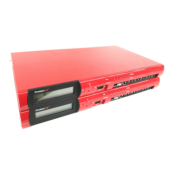
Firebox III front view (all models except Model 500 and 700) Indicators for the Firebox III Model 1000, Model 2500, and Model 4500 are on a central back-lit indicator panel. The following photograph shows the entire front view. The photograph below shows a close-up of the indicator panel. From the left, the indicators are as described on the next page. -
Page 18: Firebox Iii Front View (Model 500 And 700)
Sys A Indicates that the Firebox is running from its primary user- defined configuration. Sys B Indicates that the Firebox is running from the read-only factory default system area. Power Indicates that the Firebox is currently powered up. Security Triangle Display Indicates traffic between Firebox interfaces. - Page 19 The following photograph shows a close-up of the indicator panel. From the left, the indicators are as described below. Disarm Armed Sys A Sys B Power Disarm Red light indicates the Firebox detected an error, shut down its interfaces, and will not forward any packets. Armed Green light indicates the Firebox has been booted and is running.
-
Page 20: Firebox Iii Rear View (All Models Except Model 500 And 700)
Sys B Indicates that the Firebox is running from the read-only factory default system area. Power Indicates that the Firebox is currently powered up. Security Triangle Display Indicates traffic between Firebox interfaces. Green arrows briefly light to indicate allowed traffic between two interfaces in the direction of the arrows. -
Page 21: Firebox Iii Rear View (Model 500 And 700)
PCI Expansion Slot Reserved for future use. Factory Default This button is active only during the boot process. To boot the Firebox to SYS B, press this button and hold it down for 20-60 seconds (or until you see the Sys B light come on). Console Port Connects to the Management Station or modem through a serial cable supplied with the Firebox using PPP. - Page 22 AC Receptacle Accepts the detachable AC power cord supplied with the Firebox. Power Switch Turns the Firebox on or off. Factory Default This button is active only during the boot process. To boot the Firebox to SYS B, press this button and hold it down for 20-60 seconds (or until you see the Sys B light come on).
-
Page 23: Physical Specifications (All Models Except Model 500 And 700)
(NICs) are auto-sensing and adapt to wire speed automatically. The speed indicator lights when there is a good physical connection to the Firebox. When the card runs at 10Mbit, the speed indicator is yellow. When the card runs at 100 Mbit, the speed indicator is green. The amber traffic indicator blinks when traffic is passing through the Firebox. -
Page 24: Cross-Over Cabling
RJ-45 (Cat5) cross-over cable. Firebox System Area WatchGuard ships the Firebox III with a fixed, baseline set of functionality stored on the read-only system area of the Firebox flash disk memory. It is possible to start the Firebox using this read-only system area when the primary user area is misconfigured or corrupted. -
Page 25: Read-Only System Area
• Reset Firebox passphrases when you do not know or have forgotten them Fireboxes shipped before LiveSecurity System 4.1 shipped with the original, standard functionality called the read-only system area. Fireboxes shipped with LiveSecurity System 4.1 or later contain both the older functions and a new set of features designed to enhance usability, called the enhanced system area. - Page 26 • Primary (SysA)– Contains the Firebox software image used in normal operation and the enhanced read-only system area. • Backup– Contains the Firebox software image. Making a backup of the Firebox software To ensure that you always have a backup version of the current Firebox software, copy the image stored in the primary area to the Firebox flash disk backup area.
- Page 27 Note that this procedure is possible only when a backup image is on the backup area of the Firebox’s flash disk. There is no backup image on the Firebox until you copy one there. Click the Control Center Main Menu button (shown at right), which is located on the upper-left corner of Control Center.
- Page 28 Hardware Guide...
- Page 29 Index AC receptacle Armed light 13, 15 backup area backup image cabling cross-over using serial cable using TCP/IP certification, FCC configuration file and QuickSetup Wizard Connect To Firebox dialog box console port 17, 18 Control Center button 22, 23 cross-over cabling Disarm light 13, 15 enhanced system area...
- Page 30 traffic installation lights Armed 13, 15 Disarm 13, 15 Power 14, 16 Sys A 14, 15 Sys B 14, 16 limited hardware warranty load indicator Management Station described network, Firebox located in PCI expansion slot 17, 18 physical specifications ports 16, 17 Power light 14, 16...
Need help?
Do you have a question about the Firebox X1000 and is the answer not in the manual?
Questions and answers