
Related Manuals for Auxx Lift 2400


Summary of Contents for Auxx Lift 2400
- Page 1 Auxxlift 2400 and 2600 Auxxlift 1800 adjustment (New Motor Head) All rights reserved US Patent Design and Quality Release 07/2023/SW AUXXLIFT of the USA...
- Page 2 Important information The equipment is well-constructed and tested to safety All parts will fit together The motors are pre-adjusted for an easier adjustment If one or more parts are altered we will void the warranty The equipment is tested to the UL requirement for lifting cranes Never cut the Wire rope Never move the cable clamps on the tubes in a different position After the install check all the screws and tightness...
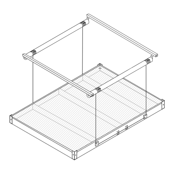
- Page 3 I. Adjustment (ADJ.) General • Prepare the adjustment. • Check your install • You want to stand underneath the controller to adjust the settings • For easier adjustment, remove the end beam. Remove the end beam Place the ladder for adjustment into this area Page 2...
-
Page 4: Motor Setup
II. Adjustment (Adj.) General • Check the location of the strut channel in relation to the motor • Wire rope falling inward Strut channel position Controller connection side Motor Left Motor connection side Green Zip-tie Wire rope routing Shape of motors Motor set-up Power Cable Bracket... - Page 5 III. Adjustment, checking your installation • Controller position • Wiring • Electrical Wire routing • Motor position (left and right) in relation to the control module • Wire Rope position • Power cord routing Left Motor Right Motor Black ADJ DM Learn Max Time Delay Time red green green red White Green...
- Page 6 IV. Adjustment in Three steps • Make sure the wire rope wraps are nicely and evenly wrapped around the motor tubes • No gaps, loops, overlays and tight • Level the long beam on both sides with a level • Don’t tighten the U-Bolts or the set screws yet. •...
- Page 7 V. Adjustment, Controller overview • Don’t use S2, S3, PT1 for the Adjustment! • During the adjustment the DeadMan (DM) is OFF! • ADJ- Mode, indicating electrical wiring and status of motors (four LED’s) • Overheat advice • Lowest point adjustment. LED3 LED2 LED1 Remote learn button red green green red...
-
Page 8: Adjustment Switches
VI. Adjustment switches • Adjustment switches are Inside / Outside • The location of Floor and Ceiling adjustment • View is always in the direction of the ceiling Floor Adjustment Outside switch Clockwise = Righty tighty Ceiling Adjustment Inside switch Clockwise = Righty tighty “... - Page 9 VII Adjustment switches for previous motors • Adjustment switches, Inside / Outside • Location of the Floor and Ceiling adjustment • View always in direction ceiling • This instruction shows only the newer motors. New Motor head Ceiling Outside Outside Adjustment switch switch...
- Page 10 VIII. Adjustment • Control the motor position • All views in direction ceiling • Location of the adjustment switch • Direction for the adjusting Wrong! Correct! Right Motor on the left side Inside Outside switch switch! + = CW All Switches are working in the same direction! Outside Outside...
- Page 11 IX. Adjustment • Extension stick, not included • Clicking during turning the switches • Unwrapping and gap advice Extension stick 3', 1m Extension stick 3', 1m Extension stick 3', 1m With an extension stick you can easy adjust the motors from the floor! Never use a drill for the adjustment! If you feel or hear a mechanical clicking or the turning of the screw is showing resistance, stop immediately turning in this direction!
- Page 12 Adjustment Step 1 Control • Control the lift assembly • All views is in direction Ceiling • Switch on ADJ Cable connector position Control the wire All LED’s on? No connection and cable connector position Switch ADJ off Advice (DeadMan off) Inside switch Tools Left Motor...
- Page 13 Adjustment Step 2 • Adjustment switches, Inside- and Outside Switches • Position for Floor and Ceiling adjustment • Indicator LED’s (Floor, Ceiling- ADJ on) • View always in direction ceiling Motor switch and wiring. Check the indicator LEDs ADJ=On, Motors are not running! Each LED indicated the Motor switch and the motor wiring! Green Green...
- Page 14 Adjustment Step 3 • Adjustment only possible when white LEDs are on • Turn in direction + / Clockwise/ Righty tighty • Don’t turn in direction - / Counter-clockwise / lefty loosy STOP DOWN LED3 LED2 LED1 White LED on White LED off Indicator LED ADJ DM...
- Page 15 Ceiling Adjustment Left Motor, Right Motor, green cable tie red cable tie Floor Ceiling Ceiling Floor Push UP and let the motors run until motor stops by themelves at your desired height or before? (NO, open Basic setting) Are the white LEDs off? Yes! White LED’s on? Activate the Controller...
- Page 16 Floor Adjustment Left Motor, Right Motor, green cable tie red cable tie Floor Ceiling Ceiling Floor Push Button DOWN and let the motors run. Do the motors stop at their desired height or before by themselves? (NO, Lock Basic setting) Are the white LED off? Yes! White LED’s on?
- Page 17 Troubleshooting: Ceiling Adjustment is too high Ceiling Stop point Scenario 1: Platform is even Ceiling Stop point Scenario 2: Platform is uneven Ceiling Stop point Page 16...
- Page 18 Scenario Top limit is too high • Push down and bring the platform to your desired height- stop • If the platform is not leveled bring the higher side of the platform to you desired height. • Switch on ADJ •...
- Page 19 Troubleshoot Floor Adjustment ( Platform is too low) Floor Stop point Floor Stop point Page 18...
- Page 20 Adjustment: too low • Push up and let the platform run until you have tension back on the rope- stop • Switch on ADJ • Turn the outside switch in direction – (minus) until the green LED switches off • Turn the same switch in direction + and switch the LED back on and stop •...
- Page 21 Troubleshooting: Lift stopped, clicking Reason: 1. Cable on the green Controller connector is loose or not connected. 2. One or more Motor adjustment switches open. 3. Motor is overheated Ceiling Stop Desired point Floor Stop Desired point • If lift stopped in position A •...
- Page 22 Basic setting motor switches Ceiling Stop point Desired Floor Stop point Basic stetting is in Green Green each position possible Inside Outside Outside Inside Controller board • C E I L I N G adjustment A • Stop the motors at your desired height toward the ceiling.
- Page 23 Check list (after installing, and than ones the year! 1. Lag screws tighten 8X 2. Cotter Pins installed and curved up 4X 3. 12mm Bracket screws tighten 4X 4. All set screws tighten 24X 5. All 6mm screws tighten 28X 6.
- Page 24 After the install, Please switch on the DEADMAN function Deadman function DEADMAN function is for your safety You push the button 1 / (UP) or 3 ↓ (DOWN) and hold it. The lift stopped immediately when you release the button at Stop the remote control or the controller.
Need help?
Do you have a question about the 2400 and is the answer not in the manual?
Questions and answers
Haven’t used the lift in about six weeks. Tried to lower it with the remote; didn’t work. Went upstairs and tried by the control box on the unit; nothing. There are no breakers blown. What do I need to do?
If the Auxx Lift 2400 does not lower using the remote or control box, follow these troubleshooting steps:
1. Switch the DEADMAN switch off and then back on.
2. Check if there is anything obstructing the lift or in the surrounding area.
3. Ensure you are holding the button in the direction of Ceiling until both motors stop by themselves.
4. Confirm that the remote control has a working battery and is connected. If the remote has lost connection or its battery is dead, the lift will stop automatically.
This answer is automatically generated