
Related Manuals for Windbit ESW3L2P Series

Summary of Contents for Windbit ESW3L2P Series
- Page 1 Windbit Hardware Installation and Reference Guide ESW3L2P Series Switches Hardware installation and reference guide Copyright © Windbit Dm3000-I Version 1.1 2023 ESW3L2P Series Switches...
-
Page 2: Legal Notice
Teldat S.A. offers no warranty whatsoever for information contained in this manual. Teldat S.A. is not liable for any direct, indirect, collateral, consequential or any other damage connected to the delivery, supply or use of this manual. ESW3L2P Series Switches... -
Page 3: Product Overview
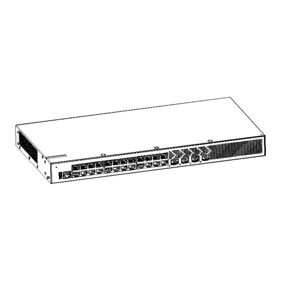
Hardware Installation and Reference Guide 1 Product Overview Windbit ESW3L2P series switches are the new-generation GE switches released by Windbit for campus access. Boasting a new hardware architecture and ESW2L3P_OS11.X modular operating system, these switches offer enhanced resource entries, accelerated hardware processing, and an improved user experience. - Page 4 Product Appearance On the front panel, the ESW3L2P-24GE4MS-E Ethernet switch is equipped with one RJ45 console port, one USB port, 24 RJ45 10/100/1000Base-T adaptive Ethernet ports, and four SFP ports. Figure 1-1 Appearance of ESW3L2P-24GE4MS-E Switch Front Panel ESW3L2P Series Switches...
- Page 5 4. 10/100/1000Base-T adaptive Ethernet port 2. USB port 5. SFP port status LED 3. Console port 6. SFP port Back Panel Figure 1-3 Back Panel of ESW3L2P-24GE4MS-E Switch Description: 1. Grounding stud 3. Power plug 2. Power cord retention clip hole ESW3L2P Series Switches...
- Page 6 The system is being initialized. green Solid green The system is operating normally. An over-temperature alarm has been System status Solid yellow Status triggered. 1. Temperature severely surpasses the threshold, prompting a system reset and Solid red restart. 2. System failure. ESW3L2P Series Switches...
- Page 7 BOOT ROM Flash Memory 64 MB SDRAM DDR4 512 MB Supported Modules Module types are subject to updates without prior notification. For detailed information, please contact Windbit. SFP Port 2500Base-X Capable 1000Base-X Capable 100Base-FX Capable Power Supply AC input: Rated voltage range: 100 V AC to 240 V AC...
- Page 8 Front Panel Figure 1-6 Front Panel of ESW3L2P-48GE4MS-E Switch Description: 1. System status LED 4. 10/100/1000Base-T adaptive Ethernet port 2. USB port 5. SFP port 3. Console port Back Panel Figure 1-7 Back Panel of ESW3L2P-48GE4MS-E Switch ESW3L2P Series Switches...
- Page 9 Regularly dust the device every three months to prevent obstruction of ventilation openings on the housing. Figure 1-8 Airflow Direction of ESW3L2P-48GE4MS-E Switch Panel Identification Status Description ESW3L2P Series Switches...
- Page 10 BOOT ROM Flash Memory 64 MB SDRAM DDR4 512 MB Supported Modules Module types are subject to updates without prior notification. For detailed information, please contact Windbit. SFP Port 2500Base-X Capable 1000Base-X Capable 100Base-FX Capable Power Supply AC input: Rated voltage range: 100 V AC to 240 V AC...
- Page 11 The ESW3L2P-24GE4MS-P switch is a Class A product and may cause radio interference in the living environment; proper measures are advised. Product Appearance The ESW3L2P-24GE4MS-P Ethernet switch is equipped with one RJ45 console port, one USB port, 24 RJ45 10/100/1000Base-T adaptive Ethernet ports, and four SFP ports. Figure 1-21 Appearance of ESW3L2P-24GE4MS-P Switch ESW3L2P Series Switches...
- Page 12 PoE power supply indicator and port rate indicator. Ensure successful switching by holding down the button for more than 2 seconds. Back Panel Figure 1-23 Back Panel of ESW3L2P-24GE4MS-P Switch Description: 1. Grounding stud 3. Power plug 2. Power cord retention clip hole Power Supply ESW3L2P Series Switches...
- Page 13 Solid red threshold, prompting a system restart. 2. A system failure has occurred. Solid green Indicates the switching status. Port LED mode LED Mode indicator Solid yellow Indicates the PoE status. 1-24 No link detected for this port. ESW3L2P Series Switches...
- Page 14 The port is actively receiving or transmitting Blinking data. SFP port status 25F-28F Optical attenuation value surpasses Solid yellow specified communication quality requirements. Optical module is in position, but module Solid red failure or optical link failure has occurred. ESW3L2P Series Switches...
-
Page 15: Preparing For Installation
2 Preparing for Installation 2.1 Safety Precautions To ensure personal safety and prevent device damage, carefully review the safety precautions before installing the Windbit ESW3L2P series switches. The following safety precautions may not encompass all possible dangers. 2.1.1 Installation Safety ⚫... -
Page 16: Electrostatic Discharge Safety
⚫ Keep indoor humidity within the recommended range. 2.1.5 Laser Safety The Windbit ESW3L2P series switches support various optical modules in the market, categorized as Class I laser products. To avoid damage, observe the following precautions: ⚫ When a fiber transceiver is operational, ensure the port is connected with a fiber-optic cable or covered by a dust cap to prevent dust and protect your eyes. -
Page 17: Installation Environment Requirements
⚫ Elevated ambient temperatures can degrade device performance and cause various hardware faults. Refer to the table below for specific temperature and humidity requirements for Windbit ESW3L2P series switches. Temperature Relative Humidity 0 ºC to 50ºC (32°F to 122°F) -
Page 18: Anti-Interference Requirements
2.2.5 Grounding Requirements Grounding is fundamental for the stable and reliable operation of the ESW3L2P series switches, playing a crucial role in preventing lightning strikes and interference. Thoroughly assess the grounding conditions at the installation site in accordance with grounding specifications, and ensure proper grounding based on the specific circumstances. - Page 19 The ground cable’s resistance should be below 1 ohm. Each switch in the ESW3L2P series is equipped with one grounding connector on the back panel, as shown in Figure 2-1.
-
Page 20: Emi Requirements
Phillips screwdriver, straight screwdriver, related Ethernet cables and fiber-optic cables, screws, Common Tools diagonal pliers, binding straps Special Tools Anti-static tools Meters Multimeter The device is delivered without a tool kit, and users should supply the listed tools accordingly. ESW3L2P Series Switches... -
Page 21: Installing The Switch
Ensure availability of the required power supply and current at the installation site. ⚫ Verify the deployment of Ethernet cables at the installation site. 3.3 Installing the Windbit ESW3L2P Series Switches Precautions Pay attention to the following points during installation:... -
Page 22: Mounting The Switch To A Rack
Ensure a secure contact between the power cord connector and the device’s power port. Fasten the power cord with retention clips after insertion. ⚫ Avoid placing any objects on the ESW3L2P series switches. ⚫ Maintain a ventilation space of more than 10 cm (3.94 in.) around the device for optimal air circulation. Do not stack multiple devices. -
Page 23: Mounting The Switch On A Wall
Extract the screws (included with the mounting bracket) from the packaging materials. Rotate the mounting brackets by 90 degrees and securely attach them to the switch using the screws. Figure 3-4 Attaching the Mounting Brackets to the Switch ESW3L2P Series Switches... -
Page 24: Mounting The Switch On A Workbench
Attach the four rubber pads to the switch’s bottom corners. Figure 3-6 Attaching the Rubber Pads to the Four Corners Place the switch on the workbench, ensuring sufficient airflow around it. Figure 3-7 Mounting the Switch on the Workbench ESW3L2P Series Switches... - Page 25 Accurately differentiate between single-mode fiber (SMF) and multi-mode fiber (MMF) optical cables and ports. ⚫ Avoid creating a small bend radius at the connector. Simple Connection Steps Connect the RJ-45 connector of the supplied Ethernet cable to the switch’s management port. Connect the other end to the management terminal. ESW3L2P Series Switches...
-
Page 26: Bundling The Cables
Check that the 100 m (328.08 ft.) Ethernet cable is routed indoors. If routed outdoors, confirm connection of the AC lightning resistance socket and network interface lightning protector. ⚫ Ensure there is a minimum clearance of 10 cm (3.94 in.) around the device. ESW3L2P Series Switches... -
Page 27: Setting Up The Configuration Environment
Configure terminal parameters: baud rate 9600, data bit 8, parity check none, stop bit 1, and flow control as none. 4.2 Powering on the Switch Checklist before Power-on ⚫ Confirm that the switch is thoroughly grounded. ⚫ Check that the power cord is properly connected. ⚫ Ensure the power supply voltage aligns with the switch requirements. ESW3L2P Series Switches... - Page 28 Check that the switch status LED indicates normal operation. ⚫ Verify the normal loading of the device’s main program. ⚫ Ensure the device’s time is consistent with the current Beijing time. ⚫ Confirm the service interface is effectively forwarding data. ESW3L2P Series Switches...
-
Page 29: General Troubleshooting Procedure
Ensure proper contact of the switch’s power powering on. Loose power cable. cord. Check for fan blockage or damage. Fan alarm Inspect the switch’s working environment, Status LED Red. Temperature alarm clean cabinet dust, and improve cooling. ESW3L2P Series Switches... - Page 30 Fiber port connection Replace optical module with a matching type. interconnected optical modules. issues. Use optical fiber compliant with requirements. Non-compliant optical fiber type. Replace optical fiber with appropriate length. Exceeding allowed optical fiber length. ESW3L2P Series Switches...
-
Page 31: Appendix A - Connectors And Connection Media
100BASE-TX/10BASE-T port. Figure A-2 Definitions of Pin Signals for a 100BASE-TX/10BASE-T Port Figure A-3 demonstrates the feasible connections of straight-through and crossover twisted-pair cables for a 100BASE- TX/10BASE-T port. Figure A-3 Twisted Pair Connections of a 100BASE-TX/10BASE-T Port ESW3L2P Series Switches... - Page 32 Windbit Hardware Installation and Reference Guide Optical Fiber Connection Select single-mode fiber (SMF) or multi-mode fiber (MMF) optical fibers based on the optical module types. Figure A-4 illustrates the optical fiber connection. Figure A-4 Optical Fiber Connection ESW3L2P Series Switches...
-
Page 33: Appendix B - Lightning Protection
LED remains Red, confirm that the arrester PE terminal is ungrounded. Installing the Ethernet Port Arrester During switch usage, connect the Ethernet port arrester to prevent lightning-induced damage before connecting the outdoor network cable. Tools: Cross or straight screwdriver, Multimeter, Diagonal pliers ESW3L2P Series Switches... - Page 34 Use a multimeter to confirm the grounding’s contact condition post-installation. ⚫ Incomplete arrester installation. If multiple ports on the switch are connected to peer devices, install arresters on all connection ports to ensure comprehensive lightning protection. ESW3L2P Series Switches...
-
Page 35: Appendix C - Cabling Recommendations In Installation
Appendix C — Cabling Recommendations in Installation When installing ESW3L2P series switches in standard 19-inch cabinets, secure cables in the binding rack on the cabinet using the cabling rack. Opt for top or bottom cabling based on the equipment room’s layout. Arrange all cable connectors in an orderly manner at the bottom of the cabinet, avoiding external exposure. - Page 36 Before bending cables, bundle them up; however, avoid placing the buckle within the bend area. This prevents significant stress on the cables, minimizing the risk of breaking cable cores, as illustrated in Figure D-3. Figure D-3 Cable bundling (3) ESW3L2P Series Switches...
- Page 37 Bundle cables of the same type in the same direction, ensuring they are clean and straight. ⚫ Use buckles based on the specifications in Table D-1 for binding cable bunches. Cable Bunch Diameter (mm) Binding Space (mm) ESW3L2P Series Switches...
- Page 38 10-30 150-200 200-300 ⚫ Ensure that there are no knots in cabling or bundling. ⚫ For solderless terminal blocks, like air switches, with cold pressing terminals, the metal part should not protrude outside the assembled terminal block. ESW3L2P Series Switches...
-
Page 39: Appendix D - Site Selection
Enhance soundproofing with a steel door. ⚫ Avoid using materials containing sulfur. ⚫ Pay attention to the air conditioner’s placement, ensuring it doesn’t blow wind directly towards devices and prevents water drops from reaching them through windows or vents. ESW3L2P Series Switches...
Need help?
Do you have a question about the ESW3L2P Series and is the answer not in the manual?
Questions and answers