
Related Manuals for Mosa GE 20 YSX


Summary of Contents for Mosa GE 20 YSX
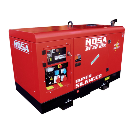
- Page 1 CE9Q30519003_EN 01-2024 Use and Maintenance Manual D5263740 Generating set GE 20 YSX Original instructions...
-
Page 3: Table Of Contents
Technical data ..........................17 Machine dimensions (mod. GE 20 YSX) ..................17 Machine dimensions (350 litre version) ....................18 Technical data (mod. GE 20 YSX) ....................19 Technical data (mod. GE 20 YSX - Single-phse) ................20 Description ............................21 Main components ..........................21 4.1.1 External components ......................21 4.1.2... - Page 4 Contents 4.1.3 Control panel and electrical panel components ..............24 Electrical protection ..........................27 4.2.1 Main machine switch ......................27 4.2.2 Residual current circuit breaker ...................27 4.2.3 Circuit breaker ........................27 4.2.4 Residual current circuit breaker with overcurrent protection (RCBO) ........27 4.2.5 Ground differential relay ......................27 4.2.6 Insulation monitor ........................28...
-
Page 5: Introduction
1. Introduction Introduction Foreword This manual supplies the Operator and qualified and authorised Technicians with technical information on the GE 20 YSX generating set (hereinafter also referred to as the "machine") produced by MOSA Div. of BCS S.p.A. (hereinafter also referred to as the "manufacturer"). In this manual, the Operator in charge and the qualified Technicians will find the indications for: • Getting familiar with the safety measures and basic standards to be adopted, to prevent hazards and damage to people, to the generating set and to the environment. -
Page 6: Supplied Documentation
(e.g. engine). Customer service The Technical Assistance and Spare Parts Service are available to the Customers. MOSA recommends that you contact the nearest authorised service centre for specialised intervention for all control and overhaul operations. In order to obtain quick and effective responses, indicate the Model and Serial Number shown on the identifi- cation plate (see “1.8 Identification data”). -
Page 7: Identification Data
1. Introduction Identification data The data identifying the generating set are given on the data plate applied in the area indicated in the figure. They are necessary for spare parts requests and communications with the Customer Service Department. D5263750 A - Manufacturer 's data Machine data • Made In: Country and year of manufacture • TYPE: Model • SERIAL N°: Serial number • Generating Set ISO 8528: Technical standard reference Machine technical data •... -
Page 8: Sound Power Level
1. Introduction Sound power level The sound power level of the generating set is given on the decal applied in the area indicated in the figure. D5263760 The value indicates the guaranteed sound power level in compliance with Directive 2000/14/EC. • Sound power level (LWA) - Unit of measurement dB(A): represents the amount of acoustic energy emit- ted in the unit of time regardless of the distance of the measuring point. -
Page 9: Safety
2. Safety Safety Safety information Always respect the warnings contained in this manual and present on the decal applied to the machine. This allows the machine to be used safely, avoiding damage to property and injury or death to people. The following words and symbols were used to identify important safety messages. -
Page 10: Positioning Of Safety Decal And Information
2. Safety Positioning of safety decal and information D5263770... -
Page 11: Decal Explanation
2. Safety 2.2.1 Decal explanation Pos. 1 Consult the manual Read the contents of the manual carefully before using the machine or carrying out maintenance operations on it. M734500253 Pos. 2 - Fire and exhaust gas inhalation hazard Fuel is highly flammable. Turn the engine off and allow it to cool before fuelling. Engine carbon monoxide emissions are highly toxic and poisonous. - Page 12 2. Safety Pos. 7 - Base liquids drainage FLUID DRAIN MCN4F40510250 Pos. 8 - Fuel filling neck M107011150 Pos. 9 - Stop the engine before servicing To avoid burns due to contact with hot parts, before carry- ing out checks or servicing of the machine, stop the engine and wait until they have cooled sufficiently.
-
Page 13: General Precautions
2. Safety General precautions Any errors during use, checks or maintenance could cause the risk of injury, even serious • Before performing the operations, read this manual and the decals applied to the machine and follow the warn- ings. If you don't understand any part of the manual, ask your Safety Officer for explanations. -
Page 14: Fire Prevention
2. Safety Fire prevention 2.4.1 Fire due to fuel, oil, coolant • Avoid approaching any flame to flammable substances such as fuel, oil, coolant. • Do not smoke or use open flames near flammable sub- stances. • Stop the generating set before refuelling. • Make sure not to spill flammable substances on over- heated surfaces or on parts of the electrical system. • After refuelling, remove any spills and tighten all filling caps tightly. -
Page 15: Handling Precautions
2. Safety Handling precautions 2.5.1 Lifting by chains or ropes • Make sure that the handling area is clear of obstacles and people. • Lift the generating set using only the lifting points provid- ed and indicated by the decals. •... -
Page 16: Transport With Towing Carriages
2. Safety • Widen the forks as much as possible to distribute the weight evenly while keeping the generating set horizon- tal. D5260120 2.5.3 Transport with towing carriages • Do not tow the machine manually or with tow vehicles without the intended towing carriage. • Check the correct assembly of the machine to the drive device. •... -
Page 17: Installation Precautions
2. Safety Installation precautions 2.6.1 Installation site precautions • Do not install machines or equipment near heat sources, in areas at risk with explosion hazard or fire hazard. Install the machine at a safe distance from fuel tanks, from flammable material (rags, paper, etc.), from chemicals. Follow the instructions of the competent authorities. • To limit potentially dangerous situations, isolate the area around the generating set, thus preventing any unauthorized personnel from getting close to it. •... -
Page 18: Precautions During Operation
2. Safety Precautions during operation • Keep the doors closed during normal operation. • Access to the internal parts of the generating set must only be carried out for maintenance purposes. • Keep the area near the muffler free from objects such as rags, paper, cartons. The high temperature of the muffler could cause the objects to burn and cause a fire. • Immediately stop the machine in case of malfunctions. Do not restart the machine without first identifying and solving the problem. -
Page 19: Maintenance Precautions
2. Safety Maintenance precautions • Maintenance must be performed by qualified personnel. • During maintenance, if unauthorized persons start the machine, there is a danger of serious personal injury or death. Do not allow unauthorized persons to approach the machine. • Stop the machine and turn the battery disconnect switch to off. • To avoid injury, do not perform maintenance with the engine running, if it is not necessary. -
Page 20: Precautions For Disposal Of Waste Material
2. Safety • Do not operate the battery without using protective gloves. The battery liquid contains corrosive sulphuric acid. D5260180 • Do not smoke, avoid open flames and sparks near the battery; exhaled vapours may cause the battery to ex- plode. D5260170 2.10 Precautions for disposal of waste material • Be sure to store the waste liquid in containers or tanks. •... -
Page 21: Technical Data
3. Technical data Technical data Machine dimensions (mod. GE 20 YSX) 1835 mm 378 mm 155 mm 770 mm 155 mm 900 mm 40 mm 820 mm 16 mm D5263780... -
Page 22: Machine Dimensions (350 Litre Version)
3. Technical data Machine dimensions (350 litre version) 1835 mm 900 mm D5264000... -
Page 23: Technical Data (Mod. Ge 20 Ysx)
3. Technical data Technical data (mod. GE 20 YSX) Rated power Three-phase stand-by power ( 20 kVA (16 kW) / 400V / 28.9A Three-phase PRP power ( 18 kVA (14.4 kW) / 400V / 26A Single-phase PRP power ( 7 kVA / kW / 230V / 30.4A Frequency 50 Hz Cosφ General specifications 100 ℓ Fuel tank capacity 350 ℓ (upon request) 100 ℓ 29.5 h Autonomy (75% PRP) 350 ℓ... -
Page 24: Technical Data (Mod. Ge 20 Ysx - Single-Phse)
3. Technical data Technical data (mod. GE 20 YSX - Single-phse) Rated power 20 kVA (16 kW) / 230V / 86.9A Single-phase stand-by power ( 20 kVA (16 kW) / 115V / 173.9A 18 kVA (14.4 kW) / 230V / 78.3A Single-phase PRP power ( 18 kVA (14.4 kW) / 115V / 156.5A Frequency 50 Hz Cosφ General specifications 100 ℓ Fuel tank capacity 350 ℓ (upon request) 100 ℓ 29.5 h Autonomy (75% PRP) 350 ℓ... -
Page 25: Description
4. Description Description The Generating Set is a machine that transforms mechanical energy, generated by an engine, into electrical energy through an alternator. Main components 4.1.1 External components D5263790... - Page 26 4. Description 1 - Control panel 2 - Control panel access door 3 - Lifting hook 4 - Radiator cap access door 5 - Rain cover for exhaust pipe 6 - Oil drain plug 7 - Coolant drain plug 8 - Fluid drain plug 9 - Engine compartment access door 10 - Electrical distribution panel 11 - Quick couplings for external fuel tank (optional)
-
Page 27: Internal Components
4. Description 4.1.2 Internal components D5263800 1 - Fuel tank 9 - Oil level dipstick 2 - Alternator 10 - Fuel filler plug 3 - Engine air filter 11 - Fuel pre-filter 4 - Fuel filter 12 - Fuel supply pump 5 - Radiator cap 13 - Battery 6 - Coolant expansion tank 14 - Battery disconnect switch 7 - Oil filler plug 15 - Base liquid leakage sensor... -
Page 28: Control Panel And Electrical Panel Components
4. Description 4.1.3 Control panel and electrical panel components Manual, automatic and single-phase versions D5263810 1 - Control panel power switch (ON-OFF) 2 - Command and control unit 3 - Main machine switch: - Residual current circuit breaker with overcurrent protection 4P 25A - 30mA - 4P 25A circuit breaker (Versions with earth leakage relay or insulation monitor) - Main machine switch - 3P 80A circuit breaker (Single-Phase Version) 4 - Connector for connection : - Remote start and stop TCM-35... - Page 29 4. Description Version with electrical distribution (sockets) D5263820 1 - Control panel power switch (ON-OFF) 2 - Command and control unit 3 - Main machine switch: - Residual current circuit breaker with overcurrent protection 4P 25A - 30mA - 4P 25A circuit breaker (Versions with earth leakage relay or insulation monitor, DGUV) 4 - Connector for connection : - Remote start and stop TCM-35 - Connection to PAC-I switchboard...
- Page 30 4. Description D5264010 1 - Auxiliary fuses and relays 2 - Earth leakage relay or Insulation monitor - Optional DGUV version: Insulation monitor 3 - 10A circuit breaker - heater protection - Optional (Version with engine heater) 4 - 10A circuit breaker - battery charger protection - Optional (Version with battery charger) 5 - Battery charge - Optional...
-
Page 31: Electrical Protection
4. Description Electrical protection 4.2.1 Main machine switch The generating set is protected against short circuits and overloads by a circuit breaker (1) located upstream of the system. Overload protection tripping is not instantaneous; it follows an overcurrent/time characteristic. The greater the overcur- rent, the shorter the tripping time. The rated tripping current refers to an operating temperature of 30°C. -
Page 32: Insulation Monitor
4. Description 1 - Ground fault current adjustment potentiometer 2 - Intervention time adjustment potentiometer 3 - Multifunction led for internal electronics fault report/inter- nal temperature out of range / potentiometer t(SES) not centred correctly 4 - Power supply presence signal led 5 - Differential relay tripped signal led 6 - Tool set-up microswitches 7 - Test button... - Page 33 4. Description SRI3/ D2 operation • ON indicator (4) indicates that the equipment is powered. • Pressing the test button (6) for at least 5 seconds, turns on the Alarm (5) and Pre-alarm (3) LEDs. • When the button (6) is released, the Pre-alarm led (3) turns off and the Alarm led (5) remains ON. Press the test button (6) again to turn off the Alarm led (5). • If the isolation resistance drops below the set pre-alarm value, the Pre-alarm led (3) lights up and the contact of the Pre-alarm relay switches.
-
Page 34: Optional Equipment And Accessories
4. Description Optional equipment and accessories 4.3.1 3-way kit for fuel supply The 3-way kit allows you to supply the engine of the generating set from the fuel tank of the machine or from an external tank of greater capacity to increase the operating range. D5260410 It consists mainly of two parts: •... -
Page 35: Remote Start/Stop Control
4. Description 4.3.2 Remote Start/Stop control Pairing the TCM 35 with the generating set allows it to be started and stopped by remote. 1 - Connect the TCM 35 remote control to the TCM 35 – PAC-I connection connector (1) via the control cable (2) on the remote control. -
Page 36: Pac Mains/Generator Switchboard
4. Description 4.3.3 PAC mains/generator switchboard Automatic version CAUTION • The PAC switchboard is supplied without connecting cables. Make the connections under safe conditions. • The installation of the PAC switchboard and all connections between the board and the com- mercial electricity grid (MAINS), the system to be powered (LOAD) and the generating set (GENERATOR) must be carried out by a qualified electrician and in accordance with the regula- tions in force in the place of installation. - Page 37 4. Description 4 - Set the command and control (1) to AUTO (automatic) mode to enable emergency operation. The emergency system will be entirely managed by the com- mand and control system (1): • No MAINS or MAINS out of limits detection • Engine start-up • GENERATOR remote control switch closing control, that is, the system is powered by the generator (after engine warm-up and check that the generator parameters are D5263860 within the limits)
-
Page 38: Pac-I Mains/Generator Switchboard
4. Description 4.3.4 PAC-I mains/generator switchboard Version with electrical distribution (sockets) CAUTION • Make the connections under safe conditions. • The installation of the PAC-I switchboard and all connections between the board and the commercial electricity grid (MAINS), the system to be powered (LOAD) and the generating set (GENERATOR) must be carried out by a qualified electrician and in accordance with the regula- tions in force in the place of installation. - Page 39 4. Description 3 - Follow the steps below for first start-up. ◦ Check that the main machine switch and other electrical protection switches are closed (switch lever up). ◦ Set the command and control unit (1) to AUT (auto- matic) mode. D5263860 ◦ Press the MAN key on the command and control unit of the PAC-I switchboard, check for the absence of danger and press the KG key to start the generating set.
- Page 40 4. Description NOTES:...
-
Page 41: Installation
5. Installation Installation WARNING • Before proceeding with the installation, carefully read section “2. Safety” - “2.6 Installation precautions” and “2.7 Precautions during operation”. • The installation and the electrical connection described in this chapter are indicative. For these operations, it is necessary to contact Specialized Technicians who must issue the necessary certifications. -
Page 42: Indoor Installation
5. Installation Indoor installation Important • The room where the generating set will be installed must comply with the legislation in force at the place of installation. Installation of the generating set indoor must be carried out in accordance with the instructions described. D5260270 Generating set Recommended minimum size... -
Page 43: Supporting Floor
5. Installation 5.3.1 Supporting floor For a correct support of the electronic unit and to avoid the transmission of vibrations, it is necessary to build a reinforced concrete platform (7) on the floor, isolated from the rest of the structure. The generating set frame must be fixed to the platform (7) with dowels or anchor bolts. The platform must have a length (D) and a width (E) greater than 400 mm (200 mm per side) with respect to the support base of the generating set (200 mm per side). -
Page 44: Grounding With Isolation Monitor
5. Installation 5.4.2 Grounding with isolation monitor In machines equipped with an insulation monitor, connection of the grounding terminal (1) to a grounding system is not required. Located on the front of the machine, the isolation monitor continuously monitors the ground insulation of the active parts. -
Page 45: Operation
6. Operation Operation WARNING • Before starting the machine, carefully read section “2. Safety”. • It is forbidden to connect the set to the public grid and/or other source of electricity. • Continuous operation at low load In general, all machinery (in particular those equipped with motors with after-treatment devic- es) must operate with a load (i.e. - Page 46 6. Operation Power factor - cos ϕ The power factor is a data that depends on the electrical characteristics of the load. It indicates the ratio between the Active Power (kW) and the Apparent Power (kVA). The apparent power is the total power required for the load, given by the sum of the active power delivered by the engine (after the alternator has transformed the mechanical power into electrical power) and the Re- active Power (kVAR) delivered by the alternator.
-
Page 47: Checks Before Start-Up
6. Operation Checks before start-up 1 - Check that the battery disconnect switch is turned ON. D5261360 2 - Check the oil, fuel and coolant levels. 3 - Check that the engine compartment, radiator and battery access doors are locked. 4 - Check that there are no oil, fuel and coolant leaks. 5 - Check that there is no flammable or dirty material around the exhaust pipe. - Page 48 6. Operation 3 - Turn the control panel power switch (2) ON. D5263900 4 - Press the start button (3) to launch the generating set start sequence. Note The start button only works in MAN mode. 5 - Before supplying a load, let the engine run for the time shown in the following table. Ambient temperature Time required ≤ -20°C...
-
Page 49: Stopping The Generating Set
6. Operation Stopping the generating set 1 - Turn off the loads connected to the generating set. 2 - Set the main machine switch (1) to OFF (insertion lever downwards). D5263890 3 - Press the stop button (7) to launch the generating set stop sequence. The engine stops at the end of the cooling cycle. For immediate stop, press the stop button (7) again. - Page 50 6. Operation NOTES:...
-
Page 51: Maintenance
7. Maintenance Maintenance WARNING • Before proceeding with maintenance, carefully read section “2. Safety”. Refuelling Use fuel, coolant and lubricants according to the ambient temperature. 7.1.1 Fuel The fuel required for stage V engines must comply with EN590 and ASTM D975. The cetane number of the fuel should be at least 45. In order to ensure an efficient and long service life of the engine, the fuel must be sulphur-free diesel fuel: •... -
Page 52: Engine Oil
7. Maintenance 7.1.2 Engine oil • To ensure adequate protection of the engine and keep it efficient for a long time, use only the recom- mended oil. Using different oils can reduce the life of the engine. • The viscosity must be appropriate to the ambient temperature. • The oil to be used must comply with the following specifications: CJ-4 Low S.A.P.S ACEA E6 Low S.A.P.S. Low S.A.P.S. (low sulphated ash, phosphorus, sulphur oil) keeps the catalyst in good working condition. SAE oil classification In the SAE classification, oils are identified according to the viscosity. -
Page 53: Coolant
7. Maintenance 7.1.3 Coolant The engine cooling system is fuelled with OAT: ENI ANTIFREEZE SPEZIAL coolant, mixed at 50% with dem- ineralised water. It is recommended to continue using the same coolant. If the type of coolant is changed for refuelling, the system must be thoroughly washed. By mixing with each other, the residues of additives of different types contained in the different liquids would create gelatinous substances that could obstruct the system. Use a mixture of 50% demineralised water and 50% low silicate ethylene glycol coolant. -
Page 54: Checking And Cleaning The Engine Air Filter
7. Maintenance 2 - Remove the cap (2) and pour the coolant into the radia- tor. 3 - Top up the liquid until it covers the pipes inside the radia- tor by about 5 mm. Note • Do not overfill the radiator; allow room for coolant expan- sion. 4 - Refit the cap (2) and tighten securely. D5263960 5 - After the top-up operations, run the engine for a short period, check the coolant level again and refill if neces-... -
Page 55: Routine Maintenance
7. Maintenance Routine maintenance WARNING • Pay the utmost attention to the generating sets equipped with an automatic or remote interven- tion system. Make sure that the generating set does not start during routine maintenance or repair opera- tions by carrying out the following operations: ◦... -
Page 56: Precautions For Generating Sets With Automatic Or Remote Start-Up
7. Maintenance Precautions for generating sets with automatic or remote start-up • Pay the utmost attention to the generating sets with automatic or remote start-up system, including: ◦ Generators in emergency service to the mains. ◦ Generators with programmable automatic test function. ◦ Generators with remote control via PC, via telephone modem or GSM modem and other communica- tion systems. -
Page 57: Storage
7. Maintenance Storage • Carefully clean the fairings and all other machine parts. • Run the machine with load every 10 days for 15-30 minutes. Doing so ensures proper lubrication of the engine, keeps the battery charged and prevents any blockage of the injection system. - Page 58 7. Maintenance NOTES:...
- Page 60 MOSA div. della BCS S.p.A. Viale Europa, 59 20047 Cusago (Milano) Italy Tel.+39 - 0290352.1 Fax +39 - 0290390466 www.mosa.it...
Need help?
Do you have a question about the GE 20 YSX and is the answer not in the manual?
Questions and answers