Vulcan-Hart VE30 Service Manual
Electric braising pans (30 & 40 gallon)
Hide thumbs
Also See for VE30:
- Replacement parts manual (25 pages) ,
- Specifications (2 pages) ,
- Installation & operation manual (56 pages)
Table of Contents
Advertisement
Quick Links
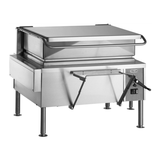
VE40 SHOWN
This Manual is prepared for the use of trained Vulcan Service
Technicians and should not be used by those not properly
qualified. If you have attended a Vulcan Service School for this
product, you may be qualified to perform all the procedures
described in this manual.
This manual is not intended to be all encompassing. If you have
not attended a Vulcan Service School for this product, you should
read, in its entirety, the repair procedure you wish to perform to
determine if you have the necessary tools, instruments and skills
required to perform the procedure. Procedures for which you do
not have the necessary tools, instruments and skills should be
performed by a trained Vulcan Service Technician.
Reproduction or other use of this Manual, without the express
written consent of Vulcan, is prohibited.
For additional information on Vulcan-Hart Company or to locate an authorized parts
and service provider in your area, visit our website at www.vulcanhart.com.
A product of VULCAN-HART
SERVICE MANUAL
ELECTRIC BRAISING PANS
(30 & 40 GALLON)
- NOTICE -
VE30
ML-126849
VE40
ML-126850
LOUISVILLE, KY 40201-0696
F35410 (May 2003)
Advertisement
Table of Contents

Related Manuals for Vulcan-Hart VE30


Summary of Contents for Vulcan-Hart VE30
- Page 1 Reproduction or other use of this Manual, without the express written consent of Vulcan, is prohibited. For additional information on Vulcan-Hart Company or to locate an authorized parts and service provider in your area, visit our website at www.vulcanhart.com. A product of VULCAN-HART...
-
Page 2: Table Of Contents
CONDENSED SPARE PARTS LIST ............32 © VULCAN 2003... -
Page 3: General
Once the product is fully cooked, the pan can be tilted for ease of product removal. Control Panel GENERAL Model Designations VE30 - 30 gallon capacity VE40 - 40 gallons capacity Standard Standard set of hand tools. VOM with an AC current tester. -
Page 4: Specifications
Lift up on the bottom edge of panel until it clears the catch. Tilt outwards and allow the panel to drop down. Reverse procedure to install. F35410 (May 2003) AMPERAGE PER LINE VE30 TOTAL L1-L3 Control Panel Remove front panel. Disconnect conduit from control box. -
Page 5: Power Supply Box Components
Tilt bottom of control panel outwards and pull down. NOTE: The control panel should be supported to remove lead wire strain. Remove control box from control panel. Disconnect lead wires from control switch. Pull temperature dial from potentiometer shaft and remove mounting nut. Control panel is removed. -
Page 6: Temperature Controller
Remove power supply box cover. Disconnect lead wires then remove the component being replaced . Reverse procedure to install the replacement component. Check braising pan for proper operation. TEMPERATURE CONTROLLER WARNING: DISCONNECT THE ELECTRICAL POWER TO THE MACHINE AND FOLLOW LOCKOUT / TAGOUT PROCEDURES. -
Page 7: Pan Position/Down Limit Switch
Check calibration as outlined under TEMPERATURE CONTROLLER CALIBRATION. PAN POSITION/DOWN LIMIT SWITCH WARNING: DISCONNECT THE ELECTRICAL POWER TO THE MACHINE AND FOLLOW LOCKOUT / TAGOUT PROCEDURES. Remove front and left side panels as outlined under COVERS AND PANELS. Remove strain relief nut from end of strain relief body and remove pan position/down limit switch from switch mounting bracket. - Page 8 Align roller arm adaptor with the four locking tabs pointing up and position one of the tabs at 0°. NOTE: The 0° position of the roller arm locking tab is the starting point for alignment only. The locking tab cannot remain at the 0° position. SIDE VIEW SHOWN Place roller arm adaptor on the gear cam to engage the teeth.
-
Page 9: Up Limit Switch
Reverse procedure from step 5 to complete the installation. Adjust pan position/down limit switch on switch mounting bracket as outlined under PAN POSITION/DOWN LIMIT SWITCH ADJUSTMENT in SERVICE PROCEDURES AND ADJUSTMENTS. UP LIMIT SWITCH WARNING: DISCONNECT THE ELECTRICAL POWER TO THE MACHINE AND FOLLOW LOCKOUT / TAGOUT PROCEDURES. -
Page 10: Dc Lift Motor
Remove the insulation cover. Loosen lock nut and remove threaded probe from pan. Reverse procedure to install and check braising pan for proper operation. F35410 (May 2003) NOTE: When installing: Route thermocouple wire in the same manner thru the metal clamps on the hinge &... -
Page 11: Gear Reducer
Loosen the strain relief nut and the hold down clamps for the motors' power cable. Pull the cable thru the strain relief opening and remove the cable from underneath the clamps. VE30 REAR VIEW SHOWN Remove motor mounting bolts from gear reducer flange. Remove motor from gear reducer. -
Page 12: Heating Elements
To install: With drive key on drive shaft, install crank assembly and tighten set screw against key. With drive key on manual crank shaft, install shaft extension coupling and tighten set screw against key. Place gear reducer in its mounting location on frame. -
Page 13: High Limit Thermostat
Reverse procedure to install and check for proper operation. HIGH LIMIT THERMOSTAT WARNING: DISCONNECT THE ELECTRICAL POWER TO THE MACHINE AND FOLLOW LOCKOUT / TAGOUT PROCEDURES. Raise the pan to the full tilt position. Remove the harness cover. Disconnect lead wires from the high limit thermostat. - Page 14 Caution: Do not release wrench while locking pin is removed or damage to the braising pan may occur. Slowly release downwards force to remove spring tension. Rotate lid spring lock nut to the next hole position then replace locking pin. Continue until all spring tension is removed, one position at a time.
-
Page 15: Service Procedures And Adjustments
SERVICE PROCEDURES AND ADJUSTMENTS WARNING: CERTAIN PROCEDURES IN THIS SECTION REQUIRE ELECTRICAL TEST OR MEASUREMENTS WHILE POWER IS APPLIED TO THE MACHINE. EXERCISE EXTREME CAUTION AT ALL TIMES. IF TEST POINTS ARE NOT EASILY ACCESSIBLE, DISCONNECT POWER AND FOLLOW LOCKOUT / TAGOUT PROCEDURES, ATTACH TEST EQUIPMENT AND REAPPLY POWER TO TEST. -
Page 16: Temperature Controller Test
12. Repeat the average temperature calculation for up to three attempts. Allow the pan to cycle at least two times between adjustments before performing the calculation. 13. If calibration is unsuccessful, the controller may be malfunctioning and cannot be adjusted properly. -
Page 17: Heating Element Test
HEATING ELEMENT TEST KW PER AMPS PER VOLTAGE ELEMENT ELEMENT 14.3 16.7 NOTES: 1. Values in the table are nominal. Tolerance is +5/-10%. 2. Voltage values are @ 60HZ. 3. Resistance values (ohms) are @ room temperature. 4. On all 208V machines, the 240V heating element is being used (KW output is reduced). -
Page 18: Pan Position/Down Limit Switch Adjustment
If voltage is present but pan does not raise, refer to MOTORIZED LIFT OPTION ONLY under TROUBLESHOOTING. If voltage is not present and the fuse is ok, turn the on/off switch off and disconnect power to the machine. 11. Install a replacement DC motor controller and check for proper operation. -
Page 19: Lid Switch Adjustment
LEFT SIDE VIEW SHOWN Adjust mounting switch bracket up or down (as necessary) to obtain the rear pan dimension of 2.25" to 2.50". 11. Repeat steps 5 thru 9 to check for proper operation. LID SWITCH ADJUSTMENT CAUTION: Lid switch should not allow pan to be raised if the lid is not opened a minimum of 23"... -
Page 20: Lid Spring Tension Adjustment
If additional adjustment is necessary, push up on the tip of the switch actuator to slightly bend the actuator around the mating edge of the trigger (cam). Verify pan will raise by operating lift control switch. Repeat the adjustment (as necessary) and check for proper operation. -
Page 21: Electrical Operation
ELECTRICAL OPERATION COMPONENT FUNCTION Temperature Controller . . . Monitors thermocouple input (type E) and regulates braising pan temperature. An external set point potentiometer is used for temperature adjustments. 120/24VAC Transformer . . . Supplies 24VAC for heating control circuit. If motorized pan lift option is installed, supplies 24VAC for lift control circuit. -
Page 22: Component Location
K1 Up Relay (3PDT) ..Supplies power to motorized lift circuit to raise the pan when 24VAC coil is energized. K2 Down Relay (3PDT) ..Supplies power to motorized lift circuit to lower the pan when 24VAC coil is energized by the lift control switch. -
Page 23: Sequence Of Operation
SEQUENCE OF OPERATION Refer to schematic diagram AI1376 for the electrical sequence of operation. Manual pan lift is the standard configuration. Heating Conditions. Braising pan connected to correct supply voltage and is properly grounded. 240-480/120VAC transformer energized. Temperature controller energized. 120/24VAC transformer energized. - Page 24 When the pan is raised 2.25" to 2.50" at the rear, pan position/down limit switch contacts change state. The N.O contacts open to remove power from K3 heat relay coil; and the N.C contacts close. Power is then available for K2 relay coil thru the N.C.
-
Page 25: Schematic Diagram
ELECTRIC BRAISING PANS - ELECTRICAL OPERATION SCHEMATIC DIAGRAM Page 25 of 32 F35410 (May 2003) -
Page 26: Wiring Diagrams
ELECTRIC BRAISING PANS - ELECTRICAL OPERATION WIRING DIAGRAMS Heating Element Circuits F35410 (May 2003) Page 26 of 32... -
Page 27: Terminal Block Wiring
ELECTRIC BRAISING PANS - ELECTRICAL OPERATION Terminal Block Wiring Page 27 of 32 F35410 (May 2003) -
Page 28: Troubleshooting
ELECTRIC HEATING (MANUAL LIFT OR MOTORIZED LIFT OPTION) SYMPTOMS Braising pan does not heat, power on light is lit and heat light is lit. Braising pan does not heat, power on light is lit but heat light is not lit. Braising pan does not heat, power on light is not lit. -
Page 29: Motorized Lift Option Only
MOTORIZED LIFT OPTION ONLY SYMPTOM Pan will not raise. Pan will not lower. POSSIBLE CAUSES Lid switch open (lid not opened) or malfunction. 120/24VAC transformer inoperative. On/off switch off or malfunction. Lift control switch malfunction (momentary on - raise). Up limit switch malfunction. K1 relay malfunction. - Page 30 ELECTRIC BRAISING PANS - TROUBLESHOOTING - N O T E S - F35410 (May 2003) Page 30 of 32...
- Page 31 ELECTRIC BRAISING PANS - TROUBLESHOOTING - N O T E S - Page 31 of 32 F35410 (May 2003)
-
Page 32: Condensed Spare Parts List
BRAISING PANS WITH MOTORIZED LIFT OPTION PART NUMBER 854495-1 Switch-Control 854671-1 Controller-Speed 854545-1 Relay-up & down (24VAC) 411496-F1 Switch-Micro (Lid) 854717-1 Switch-Micro (Up Limit) 855036-1 Transformer 240-480/120 150VA 854653-1 Motor-Gear F35410 (May 2003) VE30 & VE40 BRAISING PANS DESCRIPTION DESCRIPTION NOTES NOTE Printed in U.S.A.
Need help?
Do you have a question about the VE30 and is the answer not in the manual?
Questions and answers