Table of Contents
Advertisement
Quick Links
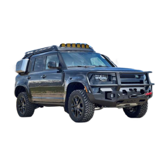
FRONT BUMPER
2020+ LAND ROVER
DEFENDER
I N S T A L L G U I D E
E X P 9 1 1
P L E A S E R E A D E N T I R E G U I D E B E F O R E I N S T A L L A T I O N
Recommended that you read this entire install guide before installation. Check that all hardware is
present before staring or scheduling an install. This guide is supplemental to mechanical knowledge and
ability. Anyone not familiar with automotive installation should seek professional installation.
LAST UPDATE 11/15/23 v1
Advertisement
Table of Contents

Related Manuals for Expedition One EXP911


Summary of Contents for Expedition One EXP911
- Page 1 FRONT BUMPER 2020+ LAND ROVER DEFENDER I N S T A L L G U I D E E X P 9 1 1 P L E A S E R E A D E N T I R E G U I D E B E F O R E I N S T A L L A T I O N Recommended that you read this entire install guide before installation.
-
Page 2: Install Guide
Expedition One does not guarantee fitment with other aftermarket products, or reinstallation of take off OEM parts. Expedition One is NOT RESPONSIBLE for damage to paint or powder coating, items assembled in error during installation or costs associated with install OEM manufacture model refreshes/updates, factory build location and suppliers may cause variations in fitment or installation and can not be verified, vehicle to vehicle . - Page 3 INSTALL GUIDE IMPORTANT INFO/FAQ I N S T A L L G U I D E A L L LIGHTPORTS To give you a wide range of options from various brands and designs, the light ports were designed to be as universal as possible.
-
Page 4: Hardware Info
INSTALL GUIDE HARDWARE INFO I N S T A L L G U I D E A L L HARDWARE Please review for details and installation. Figures or data may vary. Leave all accessible hardware loose for installation and tighten all hardware after everything is installed on the vehicle. Check and retighten all hardware after the first 100 miles and/or after off roading. -
Page 5: Hardware Guide
INSTALL GUIDE HARDWARE GUIDE I N S T A L L G U I D E E X P 9 1 1 BUMPER A Bumper Mount Bracket B Intercooler Bracket C Skid Plate D Camera Relocation Bracket E Camera Mount F OEM Fog Light Bracket Hardware Kit 1/4”... - Page 6 1 - REMOVE OEM BUMPER HARDWARE Remove the front bumper OEM hardware from the front wheel wells on each side of the vehicle. Extra locations may need to be unbolted to flex the fender liner (or completely remove the trim) for bumper removal, access and installation.
- Page 7 3 – GRILLE REMOVAL Check for any remaining hardware connecting the bumper. Undo the clips running down the edge near the headlights. Remove the center by pulling it away from the top. Save all hardware for reinstallation After the bumper is installed. 4 –...
- Page 8 5 – FENDER TRIMMING Trim the underside of the fender as shown and remove the intercooler shrouds. 6 – REINFORCEMENT BRACKET INSTALLATION Attach the reinforcement bracket to the frame as shown. Mount using the original hardware. Leave all hardware loose for adjustment.
- Page 9 6 – CONTINUED OEM HARDWARE Attach bracket to the driver side (US Market). Attach bracket to the passenger side (US Market).
- Page 10 7 – INTERCOOLER BRACKET INSTALLATION Attach the intercooler bracket on top of the frame mounts and connect to the intercoolers tabs and OEM frame point as shown. Mount using the provided 5/16” and OEM hardware. 5/16” - 18 x 1” Hex cap 5/16”...
-
Page 11: Wiring Harness
8 – LOWER BAR MOUNTING Attach the lower bar to the bumper mount bracket as shown. Mount using the provided 3/8” hardware and spacers. Use the appropriate number of spacers to secure in place. 3/8”-16 X 2 1/2” Button Head Bolt 3/8”-16 Nyloc Nut 3/8”... -
Page 12: Winch Installation
10 – WINCH INSTALLATION Mount the winch at this time using the winch manufacture provided hardware. This will mount directly to the winch mount. Adjust as needed, and see winch section for details. 11 – OEM LIGHT INSTALLATION (OPTIONAL) Attach the OEM fog lights to the provided brackets using 1/4” hardware. Mount to the light ports using the provided 5/16”... - Page 13 11 – BUMPER MOUNTING Mount the bumper as shown using the provided 1/2“ hardware. Center the bumper with the vehicle and align gaps between the body and bumper to your preference before mounting. Leave all hardware loose for adjustment. 1/2” – 13 x 1 CARRIAGE BOLT 1/2”...
- Page 14 13 – SKID PLATE MOUNTING Mount the skid plate as shown using the OEM hardware.. Locations circled below. 14 – CAMERA MOUNTING Insert the camera and washer into the provided camera mount. Attach the camera mount to the relocation bracket and secure with the provided hardware. Mount the bracket as shown to the bumper with 1/4” hardware.
- Page 15 TIGHTEN ALL HARDWARE Adjust the bumper to its desired location and TIGHTEN HARDWARE. Check that all hardware is tightened including all brackets and mounting locations. Reconnect the parking sensor wiring harness and other connections to the vehicles electronics and secure all loose wiring. Check that everything is working and adjust if needed before driving on the road.
Need help?
Do you have a question about the EXP911 and is the answer not in the manual?
Questions and answers