
Related Manuals for Scolmore ESP Aperta IP A1IPVDS


Summary of Contents for Scolmore ESP Aperta IP A1IPVDS
- Page 1 A1IPVDS Full Manual Aperta IP PoE Single Way Outdoor Station IP65 HD with Proximity Reader...
-
Page 2: Appearance Introduction
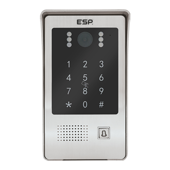
Appearance Introduction White Light LED Camera Photo Resistor Digit Button Speaker Call Button RFID Area Microphone DC Input PoE Interface Lock Control Integrated Interface (J1) RS 485 Interface (J3) Parameters Camera Sensor: Camera sensor automatically switches between day and night modes No. -
Page 3: Default Settings
Administator Operations 4.1 Default Settings: Default Administrator Passcode is 666666. Default Public Unlock Passcode is 123456. The default door opening method is RFID. The default unlock time is 2 seconds. Safe mode is turned off by default. The public unlock passcode is enabled by default 4.2 Entering Administator Mode * [ADMINISTATOR PIN] # When in Administration mode, press *, then type in the administration passcode, followed by #. - Page 4 4.2.2 Setup Unlock Mode 4.2.2.1 Card Only Unlock 3 00 # When in Administration Mode, press 3 (the call button will rapidly flash), followed by 00 #, the A1IPVDS will bleep twice to confirm Card Only Unlock has been set. 4.2.2.2 Card or Passcode Unlock 3 01 #...
- Page 5 4.2.5 Public Unlock Password Enablement 4.2.5.1 Disabling the Public Unlock Passcode 6 00 # When in Administration Mode, press 6 (the call button will rapidly flash), followed by 00 #, the A1IPVDS will bleep twice to confirm that the Public Unlock Passcode has been turned off.
-
Page 6: User Operations
User Operations 6.1 Modify User Passcode by Card * [Present User Card] [Current User Passcode] # [New User Passcode] # [New User Passcode] # Note: Default User Passcode is 0000, and cannot be used to unlock the door. This Passcode must be modified to use the User Passcode When in Standby Mode, press *, swipe the desired User card that you want to change the user code for, type in the current User Code (default is 0000), press #, then type in the new desired 4 digit Passcode press #, and then reenter this same 4 digit Passcode and finally press #. -
Page 7: Wiring Diagrams
Wiring Diagrams Connection Diagrams A1IPVDS Connections Diagram Alternative power connections Fail Secure Lock (+) NO12V+ (Red) (Orange) Video Door Station (Green) Lock Connections (Yellow) Exit button (Brown) Sensor (White) Ground (Black) 485A RS485 485B IP/PoE connection Lock Connections Reed Switch Note: Note: When using number 2 or 3 connection types, the purple line is not needed. - Page 8 System Wiring Diagrams Installation Diagrams Flush Mounting Dimensions 30mm...
-
Page 9: Installation
Mounting Diagrams Accessories A1IPVDS Quick Start Guide Aperta IP PoE Single Way Outdoor Station IP65 HD with Proximity Reader The latest product manuals and software is available online: https://www.espuk.com/technical_support REV: G23 • A1IPVDS 1 Pc • Plastic Rawl Screws 4 Pcs •... - Page 10 Contact Details Elite Security Products UK, Unit 7 Target Park, Shawbank Road, Lakeside, Redditch, Worcestershire, B98 8YN Tel: +44(0) 1527 51 51 50 Fax: +44(0) 1527 15 01 43 Email: info@espuk.com Registered in England, Company Registration Number: 02769392, VAT Registration: GB614686525 For more product information please visit www.espuk.com E&OE - Errors and Omissions Excepted.
Need help?
Do you have a question about the ESP Aperta IP A1IPVDS and is the answer not in the manual?
Questions and answers
Hi can the id cards/fobs be assigned a number so can be deleted without need the actual fob?