Morco GB24 User & Installation Instructions Manual
Hide thumbs
Also See for GB24:
- User & installation instructions manual (36 pages) ,
- User manual (9 pages) ,
- Technical instructions (44 pages)
Table of Contents
Advertisement
User & Installation Instructions
BOILER OUTPUT
To Domestic Hot Water:
GB24-Propane Minimum 8.0 kW
GB30-Propane Minimum 8.0 kW
GB24-Propane Maximum 24.2 kW
GB30-Propane Maximum 30.3 kW
12/2023
UIN 236461 A02
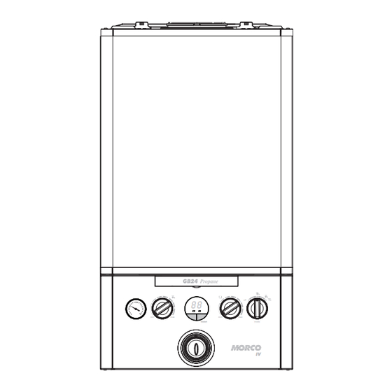
GB24 & GB30
IV
Propane
88
min
max
restart
restart
To Central Heating:
GB24-Propane Minimum 8.0 kW
GB30-Propane Minimum 8.0 kW
GB24-Propane Maximum 24.2 kW
GB30-Propane Maximum 24.2 kW
Morco House, Riverview Road, Beverley, East Yorkshire, HU17 0LD
Morco Products Ltd
Tel: 01482 325456
Website:
www.morcoproducts.co.uk
off
e
min
max
mode
IV
Email: sales@morcoproducts.co.uk
Advertisement
Table of Contents

Related Manuals for Morco GB24


Summary of Contents for Morco GB24
- Page 1 GB30-Propane Minimum 8.0 kW GB30-Propane Minimum 8.0 kW GB24-Propane Maximum 24.2 kW GB24-Propane Maximum 24.2 kW GB30-Propane Maximum 30.3 kW GB30-Propane Maximum 24.2 kW Morco House, Riverview Road, Beverley, East Yorkshire, HU17 0LD Morco Products Ltd Tel: 01482 325456 Email: sales@morcoproducts.co.uk Website: www.morcoproducts.co.uk...
- Page 2 ERP DATA MODEL SYMBOL UNITS Condensing Boiler Low Temperature Boiler B1 Boiler Cogeneration Space Heater Equipped with a Supplementary Heater Combination Heater Nominal Heat Output for Space Heating Full Load 24.3 24.3 Part Load Auxiliary Electricity Consumption Full Load 0.029 0.03 Part Load 0.022...
- Page 3 PRODUCT FICHE MORCO IV COMBINATION BOILER Morco Products Ltd ERP DATA SYMBOL UNITS MODEL Condensing boiler Seasonal Space heating efficiency class Rated heat output ƞ Seasonal space heating energy efficiency Annual energy consumption Sound power level, indoors Water heating energy efficiency class...
-
Page 5: Table Of Contents
Morco GB24 & GB30 IV Destination Country: CAT I (30 mbar) CAT II (20/37 mbar) Combination Boiler 2H3P CH = Switzerland DE = Germany CZ = Czech Republic NL = Netherlands ES = Spain CAT I (37 mbar) FR = France... -
Page 6: Users Instructions
1.1 INTRODUCTION without supervision. Children should be supervised to ensure that they The Morco GB IV is a wall mounted, room sealed, condensing combination boiler, featuring full sequence automatic spark do not play with the appliance. - Page 7 SECTION 1 - USERS INSTRUCTIONS 1.8 OPERATION 1.10 WINTERISATION Winter Conditions - (Central Heating and Domestic Hot Water required) If the holiday home or park home is to be left unoccupied during cold periods when there is a threat of freezing, the domestic hot Set the mode knob (C) to ‘...
- Page 8 SECTION 1 - USERS INSTRUCTIONS 1.14 LOSS OF SYSTEM WATER PRESSURE the pipe in which condensate can collect. The location of the blockage should be identified as closely as possible before The pressure gauge indicates the central taking further action. heating system pressure.
- Page 9 SECTION 1 - USERS INSTRUCTIONS 1.20 POINTS FOR THE BOILER USER Note. In line with our current warranty policy we would ask that you check through the Troubleshooting guide to identify any problems external to the boiler prior to requesting a service engineers visit. Should the problem be found to be other than with the appliance we reserve the right to levy a charge for the visit, or for any pre-arranged visit where access is not gained by the engineer. 1.21 TROUBLESHOOTING NO HOT WATER NO CENTRAL HEATING NO HOT WATER OR CENTRAL HEATING...
-
Page 10: Specifications
Automatic Bypass use. Daily Pump and Diverter Valve Exercise Maximum heat output in heating mode for the GB24 is 24.2 kW Mechanical 24hr Timer with 24.2 kW available for hot water production. The boiler temperature controls are visible, located in the control Maximum heat output in heating mode for the GB30 is 24.2 kW... - Page 11 SECTION 2 - GENERAL SPECIFICATIONS 2.3 WIRING DIAGRAM...
-
Page 12: Technical Data
SECTION 3 - TECHNICAL DATA TECHNICAL DATA 3.1 DATA TABLES Table 1 General Data Morco GB IV Gas Supply** - G31 - 37mbar (I G31 - 30mbar DE/NL) (I G31 - 37mbar BE/NL/PL) 2H3P Gas Supply Connection 15mm copper compression Injector Size 3.75... - Page 13 SECTION 3 - TECHNICAL DATA 3.2 BOILER DIMENSIONS, SERVICES & CLEARANCES The following minimum clearances must be maintained for is less than the length of flue required the flue must be fitted operation and servicing. from the outside. Additional space will be required for installation, depending upon Installation from inside ONLY site conditions.
-
Page 14: General Installation Requirements
SECTION 4 - GENERAL INSTALLATION REQUIREMENTS GENERAL INSTALLATION COMPARTMENT INSTALLATIONS REQUIREMENTS A compartment used to enclose the boiler should be designed and constructed specially for this purpose. 4.1 RECOMMENDATIONS An existing cupboard or compartment may be used, provided that it is modified for the purpose. Current Gas Safety (Installation and Use) Regulation or Rules in Force. - Page 15 It is NOT necessary to have a purpose provided air vent in the room or internal space in which the boiler is installed. Neither is At maximum CH output 24.2 kW (GB24) & 24.2 (GB30) at a 20ºC it necessary to ventilate a cupboard or compartment in which the differential and flow rate 17.3 l/min (GB24) &...
-
Page 16: Installation Instructions
SECTION 5 - INSTALLATION INSTRUCTIONS INSTALLATION INSTRUCTIONS 5.4 INTERNAL WIRING The boiler has been pre-fitted with a 3 amp fused approved 5.1 BOILER PACKAGING moulded 3 pin and flying lead for use with 230V 50Hz. The boilers are supplied in different packagings: If the supply cord is damaged, it must be replaced by the manufacturer, its service agent or similarly qualified persons in •... - Page 17 The flue system is part of the appliance and is approved as such. Only use the flue systems supplied by Morco. The standard flue kit (RSF303) for the Morco GB IV range is a 600mm as shown below. There is also a 900mm kit available (RSF305).
- Page 18 SECTION 5 - INSTALLATION INSTRUCTIONS 5.9 DETERMINING THE FLUE LENGTH IMPORTANT. The boiler must be installed in a vertical position in accordance to the installation instructions. STANDARD FLUE KITS Horizontal Flue Terminal RSF303 (600mm long) - contains: Flue turret, non telescopic single piece flue incorporating a terminal and inner rubber wall seal.
- Page 19 SECTION 5 - INSTALLATION INSTRUCTIONS 5.10 DETERMINING THE FLUE LENGTH FIGURE 1 REAR FLUE SIDE FLUE Cut flue length = distance from edge of turret to outside of Cut flue length = distance from edge of turret to outside of wall dimension A + 47mm.
- Page 20 SECTION 5 - INSTALLATION INSTRUCTIONS 5.12 INSTALLING THE FLUE FITTING FLUE THROUGH THE WALL 1. Ensure the seam and the outlet terminal are at the top and fitted as shown. 2. Once the flue is installed it is IMPORTANT that the white air duct protrudes from the aluminium flue collar (RSF 060) at least 17mm min 17mm.
- Page 21 SECTION 5 - INSTALLATION INSTRUCTIONS 5.13 FLUE EXTENSIONS (RSF341) - OPTIONAL For side outlet refer to section 5.9 before connecting. INNER PIPE ASSEMBLY INSTRUCTIONS 1. Make sure that ‘top hat’ on the collar (A) fits over the 3. Slide the pipe and collar assembly back into the outer rectangular form on the inner plastic pipe (B).
- Page 22 SECTION 5 - INSTALLATION INSTRUCTIONS 5.16 45º KIT RSF325 (PAIR, OPTIONAL) This optional kit can be used on both horizontal and vertical flue kits 1. Use dimensions below for calculating total length 2. When cutting extensions or flue kits always allow sufficient (+ 30mm air duct + 14mm flue duct) to allow for correct engagement in the fitting 3.
- Page 23 SECTION 5 - INSTALLATION INSTRUCTIONS ASSEMBING THE ROOF FLUE KIT - CONT’D Assembly A 2. Ensure that if the length needs to be adjusted to allow an additional 30mm added to the outer air tube length 14mm added to the inner flue length. This allows correct engagement into the vertical connector.
- Page 24 SECTION 5 - INSTALLATION INSTRUCTIONS CONDENSATE DRAIN - CONT’D..Figure 2 - Connection of a Condensate Drainage Pipe Figure 1 - Connection of Condensate Drainage Pipe to Downstream of a Sink, Basin, Bath or Shower Water Trap to Internal Soil & Vent Stack Internal Soil Vent Stack Boiler Boiler...
-
Page 25: Commissioning Instructions
If water is connected to the gas inlet point on the holiday home and then turned on, DO NOT TURN THE BOILER ON. Check that the condensate operates and the pipework for any Contact Morco Products Ltd. immediately for advice. leaks. 6.1 GENERAL 6.4 INITIAL OPERATION... - Page 26 SECTION 6 - COMMISSIONING INSTRUCTIONS THE DISPLAY The user control has two LEDs and two 7 segment displays to inform the user about the status. The display will show the status of the boiler. The LED will show the status of the flame.
-
Page 27: Servicing Schedule
CO & CO . (Refer to Section 9). If the CO/CO ratio is greater than 0.004 AND the integrity of the complete flue system and combustion circuit seals have been verified and the inlet gas pressure have been verified, then contact Morco. - Page 28 SECTION 7 - ROUTINE SERVICING INSTRUCTIONS 7.5 BOILER UPPER & LOWER FRONT PANEL REMOVAL / REPLACEMENT REMOVAL REPLACEMENT 1. Lift the lower front panel access flap. 5. Hook the upper panel onto the top retaining clips. 2. Unscrew the fixing screw, close the access flap to retain 6.
- Page 29 SECTION 7 - ROUTINE SERVICING INSTRUCTIONS 7.7 BURNER REMOVAL AND CLEANING 1. Ensure the sump is fully drained 2. Undo the two screws and remove the sump cover retaining the lower flue manifold. 3. Lift the manifold to clear the bottom sealing gasket and remove manifold.
- Page 30 SECTION 7 - ROUTINE SERVICING INSTRUCTIONS 7.9 CLEANING THE HEAT EXCHANGER Ignition / Detection Electrode Note: Make sure the condensate trap/ siphon is fully drained before cleaning. Refer to Sections 7.8. 1. Remove ignition / detection electrode. Refer to Section 7.10. 2.
- Page 31 SECTION 7 - ROUTINE SERVICING INSTRUCTIONS 7.11 REASSEMBLY Reassemble the boiler in the following order: 5. Remove the sump cover and refit the lower flue manifold as shown. 1. Ensure that the condensate trap/siphon is full of water. 6. Refit the sump cover. 2.
- Page 32 SECTION 7 - ROUTINE SERVICING INSTRUCTIONS 7.12 FINAL CHECKS Turn all controls to “ON” position and check their correct functions in both DHW & CH modes. Additional replacement of parts information can be found on our website. www.morcoproducts.co.uk...
-
Page 33: Fault Codes
SECTION 8 - FAULT CODES FAULT CODES 8.1 FAULT FINDING CHART MAIN MENU GO TO SECTION 8.2 - ‘L1’ FLOW TEMPERATURE OVERHEAT LOCKOUT GO TO SECTION 8.3 - ‘L2’ IGNITION LOCKOUT 5 RESETS WITHIN 15 MINS - ‘LC’ TURN POWER OFF AND ON GO TO SECTION 8.4 - ‘L6’... - Page 34 SECTION 8 - FAULT CODES 8.2 ‘L1’ - FLOW TEMPERATURE OVERHEAT LOCKOUT Is the Boiler and CH System filled with anti-freeze/ Fill and vent the system and open all inhibitor solution and all isolation and radiator valves isolation valves, then restart boiler open? Has the pump impellor seized? Check by engaging Is the Flow/Return differential across the...
- Page 35 SECTION 8 - FAULT CODES 8.4 ‘L6’ - FALSE FLAME LOCKOUT Restart the boiler. Does the boiler No further action required. work OK? If problem persists Remove flame detection plug from spark generator. Is Replace Spark Generator. replace PCB. there continuity between plug and PCB? Replace harness RESTART PROCEDURE - To restart boiler, press and release the restart button.
- Page 36 SECTION 8 - FAULT CODES 8.7 ‘F3’ - FAN FAULT Does the wiring from the Fan to the PCB have Rectify Wiring & secure connections at both ends and has not connections deteriorated? Does the wiring have continuity? Replace PCB Is there 230Vac at the Blue and Brown connections to the 3 way connection on the Fan? Replace Fan...
- Page 37 SECTION 8 - FAULT CODES 8.10 ‘F6’ - OUTSIDE SENSOR FAULT IMPORTANT: If no outside sensor is fitted & F6 fault is shown, replace PCB. Securely connect the wiring at both the Is the wiring securely connected at both the boiler boiler and Outside Sensor (right hand side connector) and outside sensor? Disconnect the wires to the outside sensor.
- Page 38 SECTION 8 - FAULT CODES 8.12 NO DHW BUT CH ON Does the display shows a “dH” when a hot Is hot and cold pipework crossed? tap is open? Adjust flow rates to achieve 35ºC Are the flow rates correct as per Section 3.1. Is the wiring connected temp rise and check filter fitted in between PCB and DHW...
-
Page 39: Combustion Checks
SECTION 9 - COMBUSTION CHECK COMBUSTION CHECKS FLOWCHART FOR CO LEVEL AND COMBUSTION RATIO CHECK ON COMMISSIONING A CONDENSING BOILER Important Preliminary Information on Checks The air gas ratio valve is factory-set and must not be adjusted DURING COMMISSIONING. If the boiler requires conversion to operate with a different gas family (e.g. conversion from natural gas to LPG) separate guidance is provided with the conversion kit supplied and this must be followed. - Page 40 0.2%? sampling point. Allow readings to stabilise before recording. Turn off appliance and call Morco Technical Helpline for advice The appliance must not be commissioned until problems are identified CO level less and resolved. If commissioning cannot be fully completed, the appliance than 350ppm AND CO/CO must be disconnected from the gas supply in accordance with GSIUR.
-
Page 41: 10 Warranty Conditions
This may be a Holiday Park or Caravan Dealer. They will ensure that the details reach the manufacturer of the home who will pass on the details to Morco. Once we have the details we will call the contact given and ensure the problem is resolved. - Page 42 If the boiler was retro fitted into a caravan holiday home (or similar) the Gas Safe Engineer who installed the boiler and issued the commissioning certificate must contact Morco and we will jointly arrange a resolution to the problem. The engineer will need to report the following: •...
- Page 43 NOTES...
- Page 44 For more detailed servicing information, workshop manuals, technical advice, spare parts, product training, please phone us on 01482 325456 or contact us at the address below: MORCO PRODUCTS LTD Morco House, Riverview Road, Beverley, East Yorkshire HU17 0LD TEL: 01482 325456 FAX: 01482 212869 EMAIL: sales@morcoproducts.co.uk WEBSITE: www.morcoproducts.co.uk...
Need help?
Do you have a question about the GB24 and is the answer not in the manual?
Questions and answers