Table of Contents
Advertisement
Quick Links
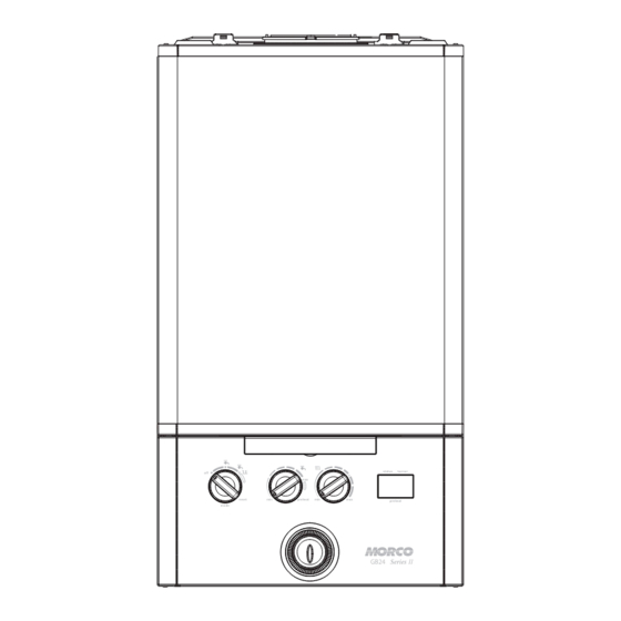
GB24 ErP & GB30 ErP
User & Installation Instructions
BOILER OUTPUT
To Domestic Hot Water:
GB24/30 Minimum 8.0 kW (27,296 Btu/h)
GB24 Maximum 24.2 kW (82,570 Btu/h)
GB30 Maximum 30.3 kW (103,384 Btu/h)
UIN 212134 A05
April 2017
Series II
off
max
reset
min
preheat
mode
To Central Heating:
GB24/30 Minimum 8.0 kW (27,296 Btu/h)
GB24/30 Maximum 24.2 kW (82,570 Btu/h)
Morco House, Riverview Road, Beverley, East Yorkshire, HU17 0LD
Morco Products Ltd
Tel: 01482 325456
Website:
www.morcoproducts.co.uk
status
burner
e
min
max
preheat
GB24
Series II
Fax: 01482 212869
Advertisement
Table of Contents

Related Manuals for Morco GB24 ErP


Summary of Contents for Morco GB24 ErP
- Page 1 GB24/30 Minimum 8.0 kW (27,296 Btu/h) GB24 Maximum 24.2 kW (82,570 Btu/h) GB24/30 Maximum 24.2 kW (82,570 Btu/h) GB30 Maximum 30.3 kW (103,384 Btu/h) Morco House, Riverview Road, Beverley, East Yorkshire, HU17 0LD Morco Products Ltd Tel: 01482 325456 Fax: 01482 212869 Website: www.morcoproducts.co.uk...
- Page 2 ERP DATA MODEL SYMBOL UNITS Condensing Boiler Low Temperature Boiler B1 Boiler Cogeneration Space Heater Equipped with a Supplementary Heater Combination Heater Nominal Heat Output for Space Heating Full Load 24.3 24.3 Part Load Auxiliary Electricity Consumption Full Load 0.042 0.031 Part Load 0.012...
- Page 3 PRODUCT FICHE MORCO COMBINATION BOILER Morco Products Ltd ERP DATA SYMBOL UNITS MODEL Condensing boiler Seasonal Space heating efficiency class Rated heat output ƞ Seasonal space heating energy efficiency Annual energy consumption Sound power level, indoors Water heating energy efficiency class...
-
Page 5: Table Of Contents
Morco GB24 & GB30 Series II Destination Country: BE = Belgium Combination Boiler CH = Switzerland CZ = Czech Republic DE = Germany ES = Spain FR = France GB = UK GR = Greece IE = Ireland IT = Italy... -
Page 6: Users Instructions
Clearances of 165mm (6 ”) above, 100mm (4”) below, The Morco GB Series II is a wall mounted, room sealed, condensing 2.5mm (1/8”) at the sides and 450mm (17 3/4”) at the front of combination boiler, featuring full sequence automatic spark ignition the boiler casing must be allowed for servicing. - Page 7 SECTION 1 - USERS INSTRUCTIONS To shut down the boiler Operation Set the mode knob control to OFF Winter conditions - i.e. CH and DHW required. To relight the boiler Ensure the mode knob control (A) is set to winter ( Repeat the procedure detailed in ‘To light the boiler’.
- Page 8 SECTION 1 - USERS INSTRUCTIONS Loss of system water pressure To unblock a frozen condensate pipe; The pressure gauge indicates the central heating system 1. Follow the routing of the plastic pipe from its exit point on the pressure. If the pressure is seen to fall below the original appliance, through its route to its termination point.
- Page 9 See boiler “Operation Modes” section. If ‘0’ is displayed then and “Fault Codes” section contact Morco if your appliance is under warranty or a Gas Safe Registered Engineer, or in Check the time settings on the other countries a qualified and...
-
Page 10: General Specifications
SECTION 2 - GENERAL SPECIFICATIONS 2.1 GENERAL SPECIFICATIONS The Morco GB Series II range of boilers are wall mounted, full The boiler contains the following components: sequence, automatic spark ignition low water content, fanned Cast Aluminium Heat Exchanger flue, high efficiency condensing combination boilers. - Page 11 SECTION 2 - GENERAL SPECIFICATIONS 2.2 WIRING DIAGRAM...
-
Page 12: Technical Data
SECTION 3 - TECHNICAL DATA Table 1 General Data Morco GB Series II Gas Supply - G31 - 37mbar (30mbar for DE) Gas Supply Connection 15mm copper compression Injector Size (mm) 3.75 3.75 Inlet Connection Domestic Hot Water G ½... - Page 13 SECTION 3 - TECHNICAL DATA BOILER DIMENSIONS, SERVICES & CLEARANCES The boiler connections are made on the boiler bulkhead fittings. (24”). Where the space into which the boiler is going to be installed is less than the length of flue required the flue must The following minimum clearances must be maintained for be fitted from the outside.
-
Page 14: General Installation Requirements
SECTION 4 - GENERAL INSTALLATION REQUIREMENTS 4.1 RECOMMENDATIONS COMPARTMENT INSTALLATIONS A compartment used to enclose the boiler should be designed Current Gas Safety (Installation and Use) Regulation or Rules in and constructed specially for this purpose. Force. An existing cupboard or compartment may be used, provided The boiler is suitable only for installation in the specified countries that it is modified for the purpose. - Page 15 SECTION 4 - GENERAL INSTALLATION REQUIREMENTS 4.4 AIR SUPPLY 4.9 REQUIREMENTS FOR SEALED WATER SYSTEMS It is NOT necessary to have a purpose provided air vent in the room or internal space in which the boiler is installed. Neither is At maximum CH output 24.2kW at a 20ºC differential and flow rate it necessary to ventilate a cupboard or compartment in which the 17.3 l/min a 3.4m wg head is available for the system...
-
Page 16: Installation Instructions
SECTION 5 - INSTALLATION INSTRUCTIONS 5.1 BOILER PACKAGING 5.4 INTERNAL WIRING The boilers are supplied in different packagings: The boiler has been pre-fitted with a 3 amp fused approved moulded 3 pin and flying lead for use with 230V 50Hz. •... - Page 17 The flue system is part of the appliance and is approved as such. Only use the flue systems supplied by Morco. The standard flue kit (RSF303) for the Morco GB range is a 600mm as shown below. There is also a 900mm kit available (RSF305).
- Page 18 SECTION 5 - INSTALLATION INSTRUCTIONS 5.7 DETERMINING THE FLUE LENGTH IMPORTANT. The boiler must be installed in a vertical position in accordance to the installation instructions. STANDARD FLUE KITS Horizontal Flue Terminal RSF303 (600mm long) - contains: Flue turret, non telescopic single piece flue incorporating a terminal and inner rubber wall seal.
- Page 19 SECTION 5 - INSTALLATION INSTRUCTIONS 5.8 DETERMINING THE FLUE LENGTH FIGURE 1 REAR FLUE SIDE FLUE Cut flue length = distance from edge of turret to outside of Cut flue length = distance from edge of turret to outside of wall dimension A + 47mm.
- Page 20 SECTION 5 - INSTALLATION INSTRUCTIONS 5.10 INSTALLING THE FLUE FITTING FLUE THROUGH THE WALL 1. Ensure the seam and the outlet terminal are at the top and fitted as shown. 2. Once the flue is installed it is IMPORTANT that the white air duct protrudes from the aluminium flue collar (RSF 060) at least 17mm min 17mm.
- Page 21 SECTION 5 - INSTALLATION INSTRUCTIONS 5.11 FLUE EXTENSIONS (RSF341) - OPTIONAL For side outlet refer to section 1.2 before connecting. INNER PIPE ASSEMBLY INSTRUCTIONS 1. Make sure that ‘top hat’ on the collar (A) fits over the 3. Slide the pipe and collar assembly back into the outer rectangular form on the inner plastic pipe (B).
- Page 22 SECTION 5 - INSTALLATION INSTRUCTIONS 5.14 FITTING THE OPTIONAL ROOF FLUE KIT (RSF345) (Pitched) Note. A 5º or 14º pitched roof plate (not supplied) is required before proceeding with the installation of this kit. This kit is suitable for both 5º and 14º pitched roof terminations, using a concentric flue to run vertically from the top of the boiler and terminating above roof level.
- Page 23 SECTION 5 - INSTALLATION INSTRUCTIONS 5.16 CONDENSATE DRAIN Internal Drain Connections Wherever possible, the condensate drainage pipe should be routed to drain by gravity to a suitable internal foul water discharge point such as an internal soil and vent stack or kitchen or bathroom waste pipe etc.
- Page 24 SECTION 5 - INSTALLATION INSTRUCTIONS CONDENSATE DRAIN - CONT’D..Figure 3 - Connection of a Condensate Pump Typical Figure 4 - Connection of Condensate Drainage Pipe to Method (see manufacturers detailed instructions) External Soil & Vent Stack Boiler Water/weather Visible air break with 75mm proof insulation Boiler...
-
Page 25: Commissioning Instructions
SECTION 6 - COMMISSIONING INSTRUCTIONS 6.2 CENTRAL HEATING CIRCUIT Before commissioning the boiler, the whole gas installation including the meter (if fitted) MUST be purged and tested for gas soundness. Fill the siphon in the condense pipework prior to operating. Purge air from the gas installation by the approved methods only. - Page 26 SECTION 6 - COMMISSIONING INSTRUCTIONS THE DISPLAY The user control has one neon and one display to inform the user about the status. The display will show the status of the boiler. The neon will show the status of the flame. If no flame is detected the neon is off.
-
Page 27: Routine Servicing Instructions
0.004 AND the integrity of the complete flue system and combustion circuit seals have been verified and the inlet gas pressure have been verified, then contact Morco. Ensure all caps and seals are re-fitted after use... - Page 28 SECTION 7 - ROUTINE SERVICING INSTRUCTIONS 7.2 BOILER UPPER & LOWER FRONT PANEL REMOVAL / REPLACEMENT REMOVAL REPLACEMENT 1. Lift the lower front panel access panel. 4. Hook the upper panel onto the top retaining clips. 2. Unscrew the two fixing screws, close the access panel to 5.
- Page 29 SECTION 7 - ROUTINE SERVICING INSTRUCTIONS 7.4 BURNER REMOVAL AND CLEANING 1. Ensure the sump is fully drained 2. Undo the two screws and remove the sump cover retaining the lower flue manifold. 3. Lift the manifold to clear the bottom sealing gasket and remove manifold.
- Page 30 SECTION 7 - ROUTINE SERVICING INSTRUCTIONS 7.6 CLEANING THE HEAT EXCHANGER Note: Ensure the condensate trap/siphon is fully drained before cleaning. Refer to Ignition Electrode Flame Detection Frames 7.5. 1. Remove ignition and flame detection electrodes. Refer to Frames 7.9 & 7.10. 2.
- Page 31 SECTION 7 - ROUTINE SERVICING INSTRUCTIONS 7.8 BURNER REMOVAL 1. Refer to Frame 7.3. 2. Undo the two screws and remove the sump cover. 3. Lift the manifold to clear the bottom sealing gasket and remove manifold. 4. Remove the 2 front fixing screws and loosen the 2 rear extended nuts.
- Page 32 SECTION 7 - ROUTINE SERVICING INSTRUCTIONS 7.10 FLAME DETECTION ELECTRODE 1. Remove the burner. Refer to Frame 7.8. 2. Check dimensions are correct as in diagram below. 3. Reassemble in reverse order. Flame Detection Electrode FOR REMOVAL: 1. Unplug the ignition lead and remove the earth lead.
-
Page 33: Fact Sheets
SECTION 8 - FACT SHEETS 8 FACT SHEETS There are a number of detailed fact sheets available for users to download from Morco’s website. Please visit www.morcoproducts.co.uk The fact sheets can be located in the troubleshooting section and include: - Winterisation of Holiday Homes... -
Page 34: Fault Codes
Check system water pressure is between 1 & 1.5bar on the system pressure gauge (G). To re- pressurise the system see Section 3. If the boiler still fails to operate then please contact Morco (if under warranty) or alternatively a Gas Safe Registered Engineer if outside of the warranty period. -
Page 36: Combustion Ratio Check
SECTION 10 - COMBUSTION CHECK FLOWCHART FOR CO LEVEL AND COMBUSTION RATIO CHECK ON COMMISSIONING A CONDENSING BOILER Important Preliminary Information on Checks The air gas ratio valve is factory-set and must not be adjusted DURING COMMISSIONING. PRIOR TO CO LEVEL AND COMBUSTION RATIO CHECK The installation instructions must have been followed, gas type verified and gas supply pressure / gas rate checked as required prior to commissioning. - Page 37 0.2%? sampling point. Allow readings to stabilise before recording. Turn off appliance and call Morco Technical Helpline for advice The appliance must not be commissioned until problems are identified CO level less and resolved. If commissioning cannot be fully completed, the appliance than 350ppm AND CO/CO must be disconnected from the gas supply in accordance with GSIUR.
-
Page 38: Warranty
SECTION 11 - WARRANTY WARRANTY CONDITIONS The boiler is guaranteed against manufacturing defects for a period of two years from the date of first commissioning. However the guarantee is subject to proof of commissioning in accordance with the Gas Safety (Installation and Use) act 1998. The guarantee does NOT cover the following issues: 1. - Page 39 NOTES...
- Page 40 For more detailed servicing information, workshop manuals, technical advice, spare parts, product training, please phone us on 01482 325456 or contact us at the address below: MORCO PRODUCTS LTD Morco House, Riverview Road, Beverley, East Yorkshire HU17 0LD TEL: 01482 325456 FAX: 01482 212869 EMAIL: sales@morcoproducts.co.uk WEBSITE: www.morcoproducts.co.uk...
Need help?
Do you have a question about the GB24 ErP and is the answer not in the manual?
Questions and answers