Table of Contents
Advertisement
Available languages
Available languages
Quick Links
Advertisement
Table of Contents

Related Manuals for electroil IMTI1.5M


Summary of Contents for electroil IMTI1.5M
- Page 1 Inverter bordo motore per uso industriale / Inverter for Industrial Motor IMTI1.5M ITTI1.5M ITA - Manuale d’Uso e Manutenzione ENG - Operation and maintenance handbook V 2.09 e successive V 2.09 and following versions EC.086.036...
-
Page 3: Table Of Contents
COLLEGAMENTO DELLA BOBINA DEL FRENO ELETTROMAGNETICO ..........10 SCHEMI ELETTRICI DEI COLLEGAMENTI ......................11 SCHEMA COLLEGAMENTI ALLA SCHEDA DI POTENZA INVERTER IMTI1.5M / ITTI1.5M...... 11 SCHEMA COLLEGAMENTI ALLA SCHEDA LOGICA PER IMTI1.5M / ITTI1.5M ........12 MESSA IN FUNZIONE E PROGRAMMAZIONE ....................13 DISPLAY ............................... -
Page 4: Generalita
Electroil. I dispositivi descritti nel presente manuale sono i seguenti: IMTI1.5M: Inverter Monofase per uso industriale per motore max 1.5kW, 7.0 Ampere. ITTI1.5M: Inverter Trifase per uso industriale per motore max 1.5kW 4.0 Ampere. L’inverter è studiato appositamente per l’azionamento di motori industriali con la finalità di garantire un perfetto controllo in retroazione di velocità, silenziosità... -
Page 5: Montaggio E Installazione
Per ulteriori informazioni fate riferimento al capitolo 2 Osservate scrupolosamente le norme vigenti di sicurezza e antinfortunistica. La tensione di rete deve corrispondere con quella prevista dall’inverter; Non sollevare o trasportare il motore collegato all’inverter facendo presa sulla scatola dell’inverter; IMTI1.5M / ITTI1.5M –- ITA ELECTROIL... -
Page 6: Dimensioni Involucro Inverter
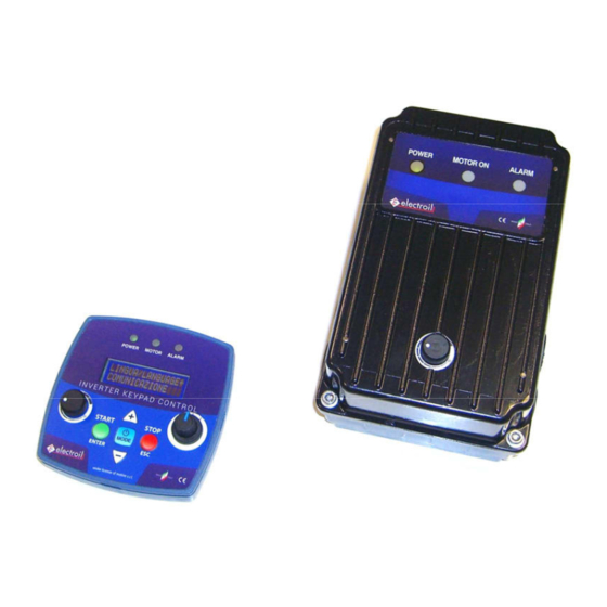
4.1 DIMENSIONI INVOLUCRO INVERTER Figura 1: Dimensioni inverter IMTI1.5M / ITTI1.5M 4.2 FUNZIONI DEL TESTIERINO (KEYPAD) E COMUNICAZIONE RADIO CON L’INVERTER Figura 2: Keypad Il tastierino (Keypad) ha una duplice funzione: IMTI1.5M / ITTI1.5M –- ITA ELECTROIL... -
Page 7: Modalità Setting - Utilizzo Del Keypad Per Impostazione Dei Parametri Dell'inverter
UTILIZZO DEL KEYPAD PER COMANDARE L’INVERTER DURANTE IL FUNZIONAMENTO COL MOTORE Di fabbrica i comandi di marcia/arresto motore per IMTI1.5M / ITTI1.5M sono remoti e fissi su direzione D1, mediante il ponticello in dotazione, collegato tra GND e D1; con Re-start abilitato (con dati di Default standard), questo consente all’inverter di avviare il motore ogni volta che viene collegato alla tensione di alimentazione da rete e viene... -
Page 8: Collegamento Dell'inverter Al Motore
Figura 3a – Collegamenti motore a Stella 4.5 COLLEGAMENTO LINEA ALIMENTAZIONE ALL’INVERTER L’alimentazione del dispositivo IMTI1.5M è di tipo monofase a 120-240Vac, 50/60Hz, mentre l’alimentazione del dispositivo ITTI1.5M è di tipo trifase 220-440Vac, 50/60Hz. E’ necessario che l’impianto a cui viene collegato l’inverter sia conforme alle normative vigenti di sicurezza: Interruttore differenziale automatico con I∆n=30mA;... -
Page 9: Collegamento Del Contatto Di Abilitazione
1.1 (1.5 Hp) 1.5 (2 Hp) Tabella 2 - Protezione magnetotermica consigliata Per IMTI1.5M collegare i N°2 fili di alimentazione Linea (L) e Neutro (N), più il conduttore di terra (GND), ai • relativi ingressi contrassegnati sulla morsettiera J2 (fig. 5) Per ITTI1.5M collegare i N°3 fili di alimentazione R,S,T ai relativi ingressi contrassegnati L1, L2, L3 (fig.5a) -
Page 10: Collegamento Di Un Ingresso Di Segnale 4/20 Ma Remoto Per Riferimento
+15V (polo 1 di J8, fig.6) e con il polo di segnale (Out) sul contatto PS1 (polo 2 di J8, fig.6). Dopo avere selezionato una delle modalità di controllo tra 5.3, 5.4 e 5.5, per regolare i livelli di uscita del trasduttore minimi e massimi e il campo di misura, nel menù selezionare: IMTI1.5M / ITTI1.5M –- ITA ELECTROIL... -
Page 11: Collegamento Di Una Ventola Ausiliaria Di Raffreddamento A 12Vdc
FUNZIONI AVANZATE->FRENO ELETTROMAGNETICO -> TENSIONE V: 104Vdc (oppure 180Vdc). Attenzione: scollegare eventuali resistenze di frenatura che precedentemente erano collegate ai morsetti BR+ e BR-, altrimenti al primo comando di start si danneggeranno irreparabilmente, con possibili ulteriori danni alle schede elettroniche. IMTI1.5M / ITTI1.5M –- ITA ELECTROIL... -
Page 12: Schemi Elettrici Dei Collegamenti
5. SCHEMI ELETTRICI DEI COLLEGAMENTI 5.1 SCHEMA COLLEGAMENTI ALLA SCHEDA DI POTENZA INVERTER IMTI1.5M / ITTI1.5M Figura 5 – Schema collegamenti scheda di potenza IMTI1.5M (Alimentazione Monofase, uscita trifase) Figura 5a - Schema scheda di potenza ITTI1.5M (alimentazione Trifase, uscita trifase) IMTI1.5M / ITTI1.5M –- ITA... -
Page 13: Schema Collegamenti Alla Scheda Logica Per Imti1.5M / Itti1.5M
5.2 SCHEMA COLLEGAMENTI ALLA SCHEDA LOGICA PER IMTI1.5M Figura 6 - Schema scheda logica IMTI1.5 M / ITTI1.5M IMTI1.5M / ITTI1.5M –- ITA ELECTROIL... -
Page 14: Messa In Funzione E Programmazione
é possibile quando i caratteri lampeggiano; al termine della variazione premere ENTER STOP/ESC Arresto motore / Per uscire dal sottomenù (entrando nel menù principale); per uscire dal menù principale abilitando i comandi motore Tabella 3: pulsanti sulla tastiera IMTI1.5M / ITTI1.5M –- ITA ELECTROIL... -
Page 15: Descrizione Delle Segnalazioni Dei Led
Impostazione della direzione 7. Rotazione 0=clockwise, 1=anticlockwise. di rotazione del rotore Funzioni Per accedere inserire la Accesso al menù Avanzate Password numerica di delle funzioni 1 ÷ 999 (richiesta accesso (numero assegnato avanzate password) dal costruttore) IMTI1.5M / ITTI1.5M –- ITA ELECTROIL... -
Page 16: Descrizione Del Menu' Delle Funzioni Avanzate
NOTA: Energia dissipata [Joule] = Potenza dissipata [Watt] x Tempo di frenatura [secondi]. IMTI1.5M / ITTI1.5M –- ITA ELECTROIL... - Page 17 1.6 bar (0.14 ÷ 232.22 psi) 0.01 ÷ 16 bar 3.5 Riferimento di pressione 0.5 bar (0.14 ÷ 232.22 psi) 0.0007 ÷ 0.2 bar 3.6 Isteresi di pressione 0.030 bar (0.01 ÷ 3 psi) IMTI1.5M / ITTI1.5M –- ITA ELECTROIL...
- Page 18 Moltiplica l’errore della proporzionale: 1. K Fattore 0 ÷ 100 grandezza di riferimento (riferimento - Fattori P.I.D. proporzionale retroazione) 2. K : Moltiplica l’integrale integrale 2. K Fattore integrale 0 ÷ 100 dell’errore (riferimento - retroazione) IMTI1.5M / ITTI1.5M –- ITA ELECTROIL...
- Page 19 A5: ZZ(Ora spegnimento 5); WW (Min spegnimento 5). Visualizza in ordine cronologico (dal Elenco allarmi primo all’ultimo) tutti gli ultimi 99 Storico Allarmi registrati eventi di Allarme, registrati durante la vita dell’inverter. Tabella 6: Menù delle funzioni avanzate IMTI1.5M / ITTI1.5M –- ITA ELECTROIL...
-
Page 20: Allarmi
La garanzia è esclusa o interrotta anticipatamente se i danni sono da imputare alle seguenti cause: Influssi esterni, installazione non professionale, inosservanza delle istruzioni per l’uso, forza maggiore, interventi da parte di sedi non autorizzate, impiego di pezzi di ricambio non originali nonché normale usura. IMTI1.5M / ITTI1.5M –- ITA ELECTROIL... -
Page 21: Dichiarazione Di Conformita' / Declaration Of Conformity
CONNECTION OF THE ELECTROMAGNETIC BRAKE COIL ..............10 WIRING DIAGRAMS .............................. 11 POWER BOARD FOR IMTI1.5M / ITTI1.5M ....................11 LOGIC BOARD FOR IMTI1.5M AND ITTI2.2M – SCHEME ................12 STARTING AND PROGRAMMING ........................13 DISPLAY ................................ 13 LIST OF COMMANDS ON THE CONTROL PANEL: ..................13 LED DESCRIPTION ............................ - Page 22 ITTI1.5M: Three-phase input supply Inverter for three-phase electric motor, 1.5 kW – 4.0A max. industrial type. IMTI1.5M is an Inverter specially designed for motor control; thanks to a perfect electric measures and rotor speed feed-back control, it assures a good speed control and good energy saving and it has many programmable functions.
- Page 23 Follow safety and accident-prevention rules carefully. power supply voltage cannot exceed the maximum admitted of the inverter; do not lift or carry the motor connected to the inverter taking the inverter box. IMTI1.5M / ITTI1.5M – ENG ELECTROIL...
- Page 24 4.1 INVERTER BOX DIMENSIONS Figura 1: Inverter box dimensions 4.2 USING OF THE KEYPAD AND RADIO COMMUNICATION WITH THE INVERTER The Keypad have a double mode of use: IMTI1.5M / ITTI1.5M – ENG ELECTROIL...
- Page 25 USB port of a PC or a Laptop, or with a specific switching power pack with USB output. The official distributor/service center of the inverter IMTI1.5M / ITTI1.5M have at least one keypad to be able to set the parameters of all the inverter of this model. It’s possible to use a only one keypad to set the parameters of more inverters IMTI1.5M.
- Page 26 1.1 (1.5 Hp) 1.5 (2 Hp) Table 2: Magnetic-Thermal protection For IMTI1.5M connect the two wires of the power supply to L (line), N (neutral) and GND on the power board • (J2 of figure 5); For ITTI1.5M connect the three wires of the power supply R,S,T on marked input L1,L2,L3 (fig. 5a) •...
- Page 27 (fig. 6). 4.7 START/STOP COMMANDS BY THE KEYPAD From the default factory settings, the start/stop commands for the IMTI1.5M / ITTI1.5M are remote wired and fixed on the direction D1, with the provided wire connected between D1 and GND.
- Page 28 Alternatively, you can connect via the serial bus RS485 one master device, checking the parameters and sends commands to the inverter via Modbus Communication Protocol (ask specific list of variables to the Technical Assistance Service). IMTI1.5M / ITTI1.5M – ENG ELECTROIL...
- Page 29 Warning: disconnect the standard braking resistors or the external resistors connected to BR1 and BR2, otherwise, at the first start of the motor, they will burn definitely, with possible damages also to the inverter electronic. IMTI1.5M / ITTI1.5M – ENG ELECTROIL...
- Page 30 WIRING DIAGRAMS 5.1 POWER BOARD FOR IMTI1.5M / ITTI1.5M Fig. 5: Power board IMTI 1.5 M (single-phase input, three phase output) Fig. 5a – Power board ITTI1.5M (Three-phase input, Three-phase output) IMTI1.5M / ITTI1.5M – ENG ELECTROIL...
- Page 31 5.2 LOGIC BOARD FOR IMTI1.5M AND ITTI2.2M – SCHEME Fig. 6 – Logic board IMTI1.5M / ITTI1.5M IMTI1.5M / ITTI1.5M – ENG ELECTROIL...
- Page 32 It allows scrolling down the items on the menu or negative change in the value of variables; the change is possible when the characters blink; after the variation press ENTER STOP/ESC To stop the motor / To exit to the function Table 3: Command list IMTI1.5M / ITTI1.5M – ENG ELECTROIL...
- Page 33 YES: to save Data setting saving or reset Saving data/ the settings default data Reset Not: to return (password NOTE: Auto-saving every time to previous required) when you exit from the menu. data settings IMTI1.5M / ITTI1.5M – ENG ELECTROIL...
- Page 34 NOTE: Braking energy [Joule] = Braking Power [Watt] x Time [second]. IMTI1.5M / ITTI1.5M – ENG ELECTROIL...
- Page 35 3.6 Pressure Hysteresis 0.030 bar (0.01 ÷ 3 psi) 0.01 ÷ 16 bar 3.7 Max Pressure 1.6 bar (0.14 ÷ 232.22 psi) 3.8 Time delay to stop at the reference 1 ÷ 120 pressure IMTI1.5M / ITTI1.5M – ENG ELECTROIL...
- Page 36 : multiply the signal error proportional Fattori P.I.D. 1. Proportional factor (reference - input) 0 ÷ 100 : multiply the integral of the integral 2. Integral factor signal error (reference - input) 0 ÷ 100 IMTI1.5M / ITTI1.5M – ENG ELECTROIL...
- Page 37 A5: ZZ(Hour switching off 5); WW (Minute switching off 5); Storing in chronological order, from Alarm first to last, of the last N°99 alarm Stored alarms history occurrences during the inverter life. Table 6: advanced menu IMTI1.5M / ITTI1.5M – ENG ELECTROIL...
- Page 38 The guarantee is excluded or interrupted in anticipation if the damage is caused to the following: External influences, non-professional installation, non-compliance with instructions, interventions by unauthorized locations, use of not original spare parts and normal wear. IMTI1.5M / ITTI1.5M – ENG ELECTROIL...
- Page 40 / ALL INFORMATION HAVE BEEN WRITTEN AND CHECKED WITH THE GREATEST CARE. WE DO NOT TAKE ANY RESPONSIBILITY FOR ANY ERRORS OR OMISSIONS. ELECTROIL srl CAN AT ITS SOLE OPTION TO CHANGE AT ANY TIME THE CHARACTERISTICS OF THE PRODUCTS SOLD. MADE IN ITALY...
Need help?
Do you have a question about the IMTI1.5M and is the answer not in the manual?
Questions and answers