Table of Contents
Advertisement
Available languages
Available languages
Quick Links
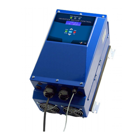
Inverter per controllo elettropompe centrifughe e di
circolazione
Inverter for centrifugal and circulating pumps control
/ Models :
Modelli
ITTP(D)11W-RS-BC
ITTP(D)15W-RS-BC
ITTP(D)22W-RS-BC
ITTP(D)30W-RS-BC
Da / From V4.01
ITA - Manuale d'Uso e Manutenzione
ENG
- Operation and maintenance handbook
EC.086.046
Advertisement
Table of Contents

Related Manuals for electroil ITTPD11W-RS-BC


Summary of Contents for electroil ITTPD11W-RS-BC
- Page 1 Inverter per controllo elettropompe centrifughe e di circolazione Inverter for centrifugal and circulating pumps control / Models : Modelli ITTP(D)11W-RS-BC ITTP(D)15W-RS-BC ITTP(D)22W-RS-BC ITTP(D)30W-RS-BC Da / From V4.01 ITA - Manuale d’Uso e Manutenzione - Operation and maintenance handbook EC.086.046...
-
Page 2: Table Of Contents
6.6 Sostituzione della batteria ....................20 7. SOLUZIONE DEI PROBLEMI PIU’ COMUNI DI INSTALLAZIONE E FUNZIONAMENTO ..21 8. GARANZIA ..........................22 9. DICHIARAZIONE DI CONFORMITA’ / DECLARATION OF CONFORMITY ......23 ITTP(D)11W– ITTP(D)15W – ITTP(D)22W – ITTP(D)30W - ITA ELECTROIL... -
Page 3: Generalita
Ponte IGBT trifase Inverter c.c. corrente continua Motore Raddrizzatore CONT Logica di controllo Inverter a microprocessore Circuito intermedio controllo ponte IGBT TRASM Linea di trasmissione con l’esterno della scheda ITTP(D)11W– ITTP(D)15W – ITTP(D)22W – ITTP(D)30W - ITA ELECTROIL... -
Page 4: Condizioni Di Esercizio
Tutti i lavori sulle apparecchiature e macchine vanno eseguiti in condizione di riposo (assenza di tensione). Modifiche e parti di ricambio Qualsiasi modifica alle apparecchiature, macchine o impianti devono essere preventivamente concordate e autorizzate dal costruttore. ITTP(D)11W– ITTP(D)15W – ITTP(D)22W – ITTP(D)30W - ITA ELECTROIL... -
Page 5: Montaggio E Installazione
(eventualmente da richiedere a parte): ITTP(D)11W: Filtro di rete EMC trifase di modo comune doppio stadio, 440V – 30A tipo DETAS TDCL30 • (codice Electroil: EF825009); ITTP(D)15W: Filtro di rete EMC trifase di modo comune doppio stadio, 440V – 42A tipo DETAS TDCL42 •... -
Page 6: Quote Di Fissaggio E Ingombri
5.2 Quote di fissaggio e ingombri: Figura 2: Quote di fissaggio a parete e ingombri ITTP(D)11W e ITTP(D)15W Figura 3: Quote di fissaggio e ingombri per ITTP(D)22W e ITTP(D)30W ITTP(D)11W– ITTP(D)15W – ITTP(D)22W – ITTP(D)30W - ITA ELECTROIL... -
Page 7: Allacciamento Idraulico Della Pompa E Dell'autoclave A Membrana
(deve avere doppio isolamento tra fase e fase e cuscinetti non conduttivi), altrimenti consigliamo di usare un filtro di uscita collegato tra uscita inverter e cavo alimentazione motore (opzionale, da richiedere al servizio clienti). ITTP(D)11W– ITTP(D)15W – ITTP(D)22W – ITTP(D)30W - ITA ELECTROIL... -
Page 8: Collegamento Elettrico Dell'inverter Alla Rete
Ponticello 2-3: collegata a massa il centro stella della terna dei condensatori di filtro attraverso un altro • condensatore più piccolo C91 (minore effetto filtrante ma diminuisce la probabilità di malfunzionamento del relè differenziale dell’impianto). ITTP(D)11W– ITTP(D)15W – ITTP(D)22W – ITTP(D)30W - ITA ELECTROIL... -
Page 9: Collegamenti Alle Schede Elettroniche
1, 2 di J14 (scheda logica – fig. 8) grandezza controllata (P,dP,V) Uscita analogica misura 0V, AO2 1, 2 di J15 (scheda logica – fig. 8) temperature Inverter Tabella 3: collegamenti Ingressi / Uscite alle schede elettroniche ITTP(D)11W– ITTP(D)15W – ITTP(D)22W – ITTP(D)30W - ITA ELECTROIL... -
Page 10: Collegamenti Per Funzionamento In Gruppo Master Slave Tramite Seriale Rs485
Contatto A- chiuso su 0V 2.00 Bar Contatto B- chiuso su 0V 1.50 Bar Contatti A- e B- contemporaneamente chiusi su 0V Tabella 4: Ingressi digitali per la selezione del set-point di riferimento di pressione ITTP(D)11W– ITTP(D)15W – ITTP(D)22W – ITTP(D)30W - ITA ELECTROIL... -
Page 11: Schema Dei Collegamenti Alle Schede Elettroniche
5.7 Schema dei collegamenti alle schede elettroniche Fig. 6: Scheda elettronica di Potenza ITTP(D)11-15W (livello inferiore) ITTP(D)11W– ITTP(D)15W – ITTP(D)22W – ITTP(D)30W - ITA ELECTROIL... - Page 12 Figura 7: Schema collegamenti scheda di potenza per ITTP(D)22-30W (livello inferiore) ITTP(D)11W– ITTP(D)15W – ITTP(D)22W – ITTP(D)30W - ITA ELECTROIL...
-
Page 13: Messa In Funzione E Programmazione
RESET da menu oppure tramite un RESET rapido: RESET: premere “STOP” e “–“ contemporaneamente per 5 secondi. I dati impostati manualmente vengono sempre salvati automaticamente ad ogni uscita dal menu delle funzioni e dopo il Check di autoregolazione. ITTP(D)11W– ITTP(D)15W – ITTP(D)22W – ITTP(D)30W - ITA ELECTROIL... -
Page 14: Prima Messa In Funzione Dell'inverter - Procedura Di Check (Auto-Apprendimento)
Diminuisce la pressione di riferimento durante il funzionamento. STOP/ESC Per spegnere il motore / per uscire dal sottomenù (entrando nel menù principale); per uscire dal menù principale abilitando i comandi motore Tabella 5: Pulsanti ITTP(D)11W– ITTP(D)15W – ITTP(D)22W – ITTP(D)30W - ITA ELECTROIL... -
Page 15: Descrizione Dei Led Del Pannello Di Controllo
Parametro non attivo per controllo secco [%] di press Differenziale; Potenza arresto per 10 .. 100% funzionamento a secco – (valore % riferito a quello misurato durante il check iniziale, eseguito a mandata chiusa). ITTP(D)11W– ITTP(D)15W – ITTP(D)22W – ITTP(D)30W - ITA ELECTROIL... -
Page 16: Descrizione Del Menu Delle Funzioni Avanzate
Corrente dispers. [A] (100.120 Ohm) al posto di quelle in dotazione. 1 .. 9.9 A 8. Corrente dispersa max. [A] I valori in % sono riferiti ai valori nominali. ITTP(D)11W– ITTP(D)15W – ITTP(D)22W – ITTP(D)30W - ITA ELECTROIL... - Page 17 14. Velocità minima per intervento 50..110% protezione rottura tubazioni 15. Pressione massima per intervento 20..110% protezione rottura tubazioni 16. Ritardo arresto pompa per 1..999 s 300 s protezione rottura tubazioni ITTP(D)11W– ITTP(D)15W – ITTP(D)22W – ITTP(D)30W - ITA ELECTROIL...
- Page 18 Mese [MM] Questa regolazione è importante per Anno [aa] Aggiorna data Ore [oo] controllo pompa mediante Timer, e Minuti [mm] con pompe in gruppo Master-Slave, Secondi [ss] per gestire l’alternanza oraria. ITTP(D)11W– ITTP(D)15W – ITTP(D)22W – ITTP(D)30W - ITA ELECTROIL...
-
Page 19: Allarmi
Valore di picco di corrente elevato sulla fase U (protez. hardware di un opto-driver). Auto-ripristinante; blocco dopo 10 interventi consecutivi. Picco corrente fase V Valore di picco di corrente elevato sulla fase V (protez. hardware di un opto-driver). Auto-ripristinante; blocco dopo 10 interventi consecutivi. ITTP(D)11W– ITTP(D)15W – ITTP(D)22W – ITTP(D)30W - ITA ELECTROIL... -
Page 20: Funzionamento In Gruppo
3. Attendere il completo spegnimento del led interno che indica la carica dei condensatori prima di toccare qualsiasi parte delle schede elettronica; 4. Estrarre la batteria presente sotto il coperchio dell’inverter ed inserire la nuova. ITTP(D)11W– ITTP(D)15W – ITTP(D)22W – ITTP(D)30W - ITA ELECTROIL... -
Page 21: Soluzione Dei Problemi Piu' Comuni Di Installazione E Funzionamento
Stop e – per 5 secondi) e rifare una procedura di check in condizioni corrette di flusso nullo in mandata, riprovando poi il funzionamento. Verificare inoltre che la valvola di non ritorno a monte del trasduttore di pressione non presenti perdite. ITTP(D)11W– ITTP(D)15W – ITTP(D)22W – ITTP(D)30W - ITA ELECTROIL... -
Page 22: Garanzia
La garanzia è esclusa o interrotta anticipatamente se i danni sono da imputare alle seguenti cause: Influssi esterni, installazione non professionale, inosservanza delle istruzioni per l’uso, interventi da parte di sedi non autorizzate, impiego di pezzi di ricambio non originali nonché normale usura. ITTP(D)11W– ITTP(D)15W – ITTP(D)22W – ITTP(D)30W - ITA ELECTROIL... -
Page 23: Dichiarazione Di Conformita' / Declaration Of Conformity
6.5.2 Pumps controlled by inverters communicating with Radio Blue-Connect system ... 20 6.6 Replacing the lithium battery....................20 SOLUTION OF THE MOST COMMUN PROBLEMS DURING INSTALLING AND WORKING .. 21 GUARANTEE ..........................22 DICHIARAZIONE DI CONFORMITA’ / DECLARATION OF CONFORMITY ......23 ITTP(D)11W– ITTP(D)15W – ITTP(D)22W – ITTP(D)30W - ENG ELECTROIL... - Page 24 TRASM Figure 1: structure of a frequency converter c.a. alternate current IGBT three-phases module c.c. direct current Motor Rectifier CONT control logic IGBT Driver circuit TRASM external line for data transmission ITTP(D)11W– ITTP(D)15W – ITTP(D)22W – ITTP(D)30W - ENG ELECTROIL...
- Page 25 Every machine, equipment or system alteration must be authorized by the manufacturer. For your safety, it is important to use only original spare parts. The use of non-original components may endanger others and can lead to loss of warranty. ITTP(D)11W– ITTP(D)15W – ITTP(D)22W – ITTP(D)30W - ENG ELECTROIL...
- Page 26 All Inverters are up to EMC legislation standards. Its works under the emission limits in industrial applications, and also in civil applications if equipped with this line filters (if it’s necessary, please ask separately): ITTP(D)11W: EMC three-phase filter common mode, double-stage, 440V – 30A type DETAS TDCL30 (Electroil •...
- Page 27 5.2 Fixing dimensions: Figure 2: Fixing dimensions for ITTP(D)11W and ITTP(D)15W Figure 3: : Fixing dimensions for ITTP(D)22W and ITTP(D)30W ITTP(D)11W– ITTP(D)15W – ITTP(D)22W – ITTP(D)30W - ENG ELECTROIL...
- Page 28 (may have a double phase-phase electrical insulation and not conductive rolling bearings) otherwise we suggest to use the specific output filter (optional – ask our sales service) connecting it between the inverter output and the motor pump voltage supply cable. ITTP(D)11W– ITTP(D)15W – ITTP(D)22W – ITTP(D)30W - ENG ELECTROIL...
- Page 29 Jumper 2-3: Grounded star point capacitors with a little capacitor C91 (lower filtering effect but decreases • the probability of malfunction of the system differential relay). ITTP(D)11W– ITTP(D)15W – ITTP(D)22W – ITTP(D)30W - ENG ELECTROIL...
- Page 30 1, 2 of J14 (logic board – fig. 8) controlled quantity (P,dP,V) Analog output for the Inverter 0V, AO2 1, 2 of J15 (logic board – fig. 8) temperature Table 3: Input / Output board connections ITTP(D)11W– ITTP(D)15W – ITTP(D)22W – ITTP(D)30W - ENG ELECTROIL...
- Page 31 Contact A- closed on 0V 2.00 Bar Contact B- closed on 0V 1.50 Bar Contact A- and B- contemporary closed on 0V Table 4: Digital input for the selection of the reference pressure ITTP(D)11W– ITTP(D)15W – ITTP(D)22W – ITTP(D)30W - ENG ELECTROIL...
- Page 32 5.7 Electronic Board connections Fig. 6: ITTP(D)11-15W Electronic power board connections (down level) ITTP(D)11W– ITTP(D)15W – ITTP(D)22W – ITTP(D)30W - ENG ELECTROIL...
- Page 33 Figura 7: ITTP(D)22-30W Electronic power board connections (down level) ITTP(D)11W– ITTP(D)15W – ITTP(D)22W – ITTP(D)30W - ENG ELECTROIL...
- Page 34 RESET of the data memory pressing buttons STOP and – at the same time during 5 seconds. All data are automatically saved every time that the user exit from the menu and after every check procedure. ITTP(D)11W– ITTP(D)15W – ITTP(D)22W – ITTP(D)30W - ENG ELECTROIL...
- Page 35 It allows scrolling down the items on the menu or negative change in the value of variables; after the variation press ENTER. Decrease the reference pressure during functioning. STOP/ESC Pump stop / To exit to the function and automatically saving Table 5: List of commands on the control panel ITTP(D)11W– ITTP(D)15W – ITTP(D)22W – ITTP(D)30W - ENG ELECTROIL...
- Page 36 [ON/OFF] and hydraulic curves of the motor- ON/OFF pump. MIN: minimum output value pressure 1.0 .. 10 mA 4 mA Sensor data MIN [ mA; V] transducer ITTP(D)11W– ITTP(D)15W – ITTP(D)22W – ITTP(D)30W - ENG ELECTROIL...
- Page 37 7. Joule braking [J] external resistors (100..120 8. Leakage Current [A] Ohm) instead of the standard included. 1 .. 9.9 A 8. Maximum leakage current [A] Values % on respect the nominal values ITTP(D)11W– ITTP(D)15W – ITTP(D)22W – ITTP(D)30W - ENG ELECTROIL...
- Page 38 14. Minimum speed value for the broken pipe protection 20..110% 15. Maximum pressure value for the broken pipe protection 1..999 s 300 s 16. Delay time for the pump stop with broken pipes protection ITTP(D)11W– ITTP(D)15W – ITTP(D)22W – ITTP(D)30W - ENG ELECTROIL...
- Page 39 P1 (start 1) ON/OFF possible untill N°7 Timer (start/stop A1 (stop 1) start/stop, setting in this format: programming) … Day : Month – Hour : Minute P7 (start 7) A7 (stop 7) ITTP(D)11W– ITTP(D)15W – ITTP(D)22W – ITTP(D)30W - ENG ELECTROIL...
- Page 40 High pick value of the current on phase V. Automatic re-start; final stop after 10 consecutive events Current Peak phase W High pick value of the current on phase W. Automatic re-start; final stop after 10 consecutive events ITTP(D)11W– ITTP(D)15W – ITTP(D)22W – ITTP(D)30W - ENG ELECTROIL...
- Page 41 3. Wait for the complete shutdown of the led which indicates the charge of capacitors before touching any part of electronic boards; 4. Replace the battery present under the cover of the inverter. ITTP(D)11W– ITTP(D)15W – ITTP(D)22W – ITTP(D)30W - ENG ELECTROIL...
- Page 42 ON, then exit to the menu and press START). When the check finish try to work again high flow, and then re- testing the minimum flow stop condition of the motor that must be with a small flow. start and stop again, continuously ITTP(D)11W– ITTP(D)15W – ITTP(D)22W – ITTP(D)30W - ENG ELECTROIL...
- Page 43 The guarantee is excluded or interrupted in anticipation if the damage is caused to the following: External influences, non-professional installation, non-compliance with instructions, interventions by unauthorized locations, use of not original spare parts and normal wear. ITTP(D)11W– ITTP(D)15W – ITTP(D)22W – ITTP(D)30W - ENG ELECTROIL...
- Page 44 / ALL INFORMATION HAVE BEEN WRITTEN AND CHECKED WITH THE GREATEST CARE. WE DO NOT TAKE ANY RESPONSIBILITY FOR ANY ERRORS OR OMISSIONS. ELECTROIL srl CAN AT ITS SOLE OPTION TO CHANGE AT ANY TIME THE CHARACTERISTICS OF THE PRODUCTS SOLD. MADE IN ITALY ITTP(D)11W–...
Need help?
Do you have a question about the ITTPD11W-RS-BC and is the answer not in the manual?
Questions and answers