Advertisement
Available languages
Available languages
Quick Links
Advertisement

Related Manuals for Nordcap Moretti Forni iDeckSeries


Summary of Contents for Nordcap Moretti Forni iDeckSeries
- Page 1 Bedienungsanweisung MORETTI Elektro-Pizzaofen Serie iDeck 2022-10...
- Page 2 PM 60.60 ¨ iD/M 60.60 ¨ PD 60.60 ¨ iD/D 60.60 ¨ ¨ ¨ PM 72.72 iD/M 72.72 PD 72.72 ¨ iD/D 72.72 ¨ PM 65.105 ¨ iD/M 65.105 ¨ ¨ ¨ PD 65.105 iD/D 65.105 ¨ ¨ PM 105.105 iD/M 105.105 PD 105.105 ¨...
- Page 3 Via A.Meucci, 4 - 610 37 - Mondolfo (PU) ITALIA Tel. +39 -07 21 -961 61 - Fax +39 -0 72 1-96 16 299 H t t p : / / w w w . m o r e t t i f o r n i . c o m e - m a i l : i n f o @ m o r e t t i f o r n i .
- Page 4 We declare under sole responsability that the products to which this declaration relates is in conformity with the following standards <> following the provisions of the directives<>.
-
Page 5: Table Of Contents
INHALTSVERZEICHNIS 01 TECHNISCHE ANGABEN 02 INSTALLATION 03 BETRIEB 04 WARTUNG 05 AUSSERORDENTLICHE WARTUNG 06 ERSATZTEILKATALOG Herzlichen Glückwunsch zum Kauf dieses exklusiven Geräts. Sie haben eine Ausstattung mit den besten technischen Eigenschaften in Verbindung mit maximalem Bedienkomfort gewählt. Wir wünschen Ihnen vollkommene Zufriedenheit. Anmerkung: Vorliegender Handbuch ist in fünf Sprachen ausgeführt. -
Page 6: Technische Angaben
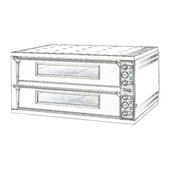
TECHNISCHE ANGABEN BESCHREIBUNG DES GERÄTES Das Gerät besteht aus einem Backelement (Backofen) und aus einem eventuellen Gärschrank oder Gestell. Das Backelement kann aus 1 oder 2 Backöfen bestehen, die voneinander vollkommen unabhängig sind. (PM-PD) Die Temperatur wird mechanisch geregelt und von zwei ACHTUNG! Vorhandensein von gefährlicher Spannung. - Page 7 Mindestabstand von 50 cm von der linken und der rechten Wand 2.5.2.1 ELEKTROANSCHLUSS BACKKAMMER sowie der Rückwand aufgestellt werden (Abb. 6). Dieser Abstand ACHTUNG! Für jedes einzelne Backelement muss von 50 cm ist unverzichtbar zur Gewährleistung des Zugangs im ein vierpoliger Hauptschalter mit Sicherungen oder ein Fall von Wartungsarbeiten.
-
Page 8: Betrieb
Stromversorgung sein. Mit dem Kabeldurchlass könen Kabel - der Elektroanschluss und die Erdung ordnungsgemäß mit einem Durchmesser zwischen 10 und 14mm blockiert durchgeführt wurden; werden. - der Anschluss und die Ableitung der Abdampfleitung Der Gärschrank wird mit einer Spannung von V230 1N 50/60 Hz ordnungsgemäß... - Page 9 Die gewünschte Backtemperatur mit Hilfe der Thermostate 10. Sicherheitsthermostat unterer Kammer (Reset) auf der Grund- und Deckenplatte (1 und 2 – 8 und 9) 11. Sicherheitsthermostat oberer Kammer (Reset) einstellen. Die Kontrolllampen 4 und 5 – 11 und 12 (Abb. 16 A B) leuchten auf und zeigen an, dass die oberen und ANMERKUNG: Diese elektronische Ausrüstung...
-
Page 10: Wartung
Unterbrechen Sie die Stromversorgung der Kammer mit der a) Den Gärschrank durch Drehen des Thermostates einschalten Starttaste (Abb. 27 und 28 Abs. 7): eine rote LED oben rechts (Abb. 17 Teil 3). Die Leuchtdiode schaltet sich ein (Abb. 17 erlischt. Teil 1). -
Page 11: Ausserordentliche Wartung
ACHTUNG DIE FOLGENDEN ANWEISUNGEN ZUR “AUSSERORDENTLICHEN WARTUNG” RICHTEN SICH AUSSCHLIESSLICH AN FACHPERESONAL MIT ORDENTGEMÄSSER LIZENZ, DAS VOM HERSTELLER ANERKANNT UND BEFUGT IST. AUSSERORDENTLICHE WARTUNG 5.3.2 AUSTAUSCH DER GEHÄRTETEN SCHEIBE Nachdem die Vorschriften von Punkt 5.1 ausgeführt wurden, ist EINLEITENDE SCHUTZMASSNAHMEN beim Austausch der Scheibe folgendermaßen vorzugehen: - Die frontseitige Tür öffnen (Teil 3 Taf. - Page 12 - Entnehmen Feder, nachdem 5.3.7 AUSTAUSCH DES PYROMETERS Befestigungsschraube und den gelochten Befestigungsflansch MODELL ELEKTROMECHANISCHE entfernt haben. Nach Durchführung der unter Punkt 5.1 genannten Vorgänge ist beim Austausch des Pyrometers folgendermaßen vorzugehen: ACHTUNG! Vertauschen Sie die Positionen der - die Feststellschrauben beim Bedienfeld ausschrauben Befestigungsschrauben der Klappe nicht, da die linke ein - den Sensor des Pyrometers im Kammerinneren entnehmen, linksgängiges Gewinde aufweist.
-
Page 13: Ersatzteilkatalog
- Den Transformator austauschen. 5.4.8 AUSTAUSCH DER WIDERSTÄNDE - Bei der Remontage in umgekehrter Reihenfolge vorgehen. Nachdem die Vorschriften von Punkt 5.1 ausgeführt wurden, ist beim Austausch der Widerstände folgendermaßen vorzugehen: 5.3.13 AUSTAUSCH DES HAUPTSCHALTERS - Die Fixierschrauben losschrauben. - Die Zuleitung der Widerstände abnehmen. MODELL ELECTRONIC Nach Durchführung der unter Punkt 5.1 genannten Vorgänge ist - Die Widerstände entnehmen ( Teil 10 Taf. - Page 14 INDEX 01 TECHNICAL SPECIFICATIONS 02 INSTALLATION 03 OPERATION 04 ORDINARY MAINTENANCE 05 SPECIAL MAINTENANCE 06 LIST OF SPARE PARTS Congratulations on the purchase of this exclusive Made in Italy device. You chose the equipment that combines the best technical qualities with maximum ease of use.
- Page 15 TECHNICAL SPECIFICATIONS WARNING! Presence of dangerous tension. Before performing any maintenance operation, disconnect the power supply by turning off DESCRIPTION OF THE APPLIANCE the switches fitted on the outside of the oven and/or the leavening The appliance comprises a cooking element (oven) and an optional compartment and wait for the appliance to cool to room temperature.
- Page 16 - insert the respective nuts from the inside of the legs, Insert a cable with an adequate cross-section (see TAB. 1) into the cable - lock the whole assembly so that it is perfectly square and flat. raceway provided (item B – fig. 11) and connect it to the terminal board Detail C as shown in figure 12 (72.72/65.105/105.105/105.65) and figure 26 - bring the top tubular side elements up to the legs (the hole furthest...
- Page 17 10. Pyrometer indicating the temperature of the top chamber NOTE: The device selected should be in the immediate vicinity 11. On/off indicator light for the heating elements in the FLOOR of the of the appliance and within easy access. top chamber The vapour aspiration hood is delivered with a voltage of V230 1N 50/60 12.
- Page 18 again. NOTE: The electronic controls allow more precise and rapid - Increase the temperature to 150°C and leave the chamber operating regulation of the oven. However, they are by nature more delicate for about 2 hours. If there is a great deal of steam inside the chamber, than traditional ones.
- Page 19 Every day, at the end of operations and after leaving the appliance to cool down, carefully remove from all parts of the oven, any residues that might have collected during cooking, using a damp sponge or cloth and a little soapy water, if necessary. Rinse and dry the areas, being sure to wipe parts with satin finish in the direction of the finish.
- Page 20 WARNING FOLLOWING INSTRUCTIONS, WHICH CONCERN “SPECIAL MAINTENANCE” ARE STRICTLY RESERVED TO SPECIALIST TECHNICIANS WITH THE RELEVANT LICENSE AS WELL AS BEING APPROVED BY THE MANUFACTURER. SPECIAL MAINTENANCE - Lift the refractory floor (item 20 plate A-C and item 27 plate B-D) using a screwdriver as a lever.
- Page 21 - Remove the side panel by unfastening the four fixing screws; WARNING! Regularly grease the screws fastening the door - Remove the inner casing and the rock wool insulation; on the right side near to the control panel, using food grease for high - Unfasten the thermocouple fixing nut;...
- Page 22 - remove the thermostat sensor located inside the compartment (item 7 Plate C) - replace the thermostat and the relative sensor - perform the above operations in reverse order to reassemble 5.4.7 REPLACING THE YELLOW INDICATOR LIGHT AND THE LIGHT SWITCH After carrying out the operations described in 5.1 above, to replace the yellow indicator light and the light switch proceed as follows: - remove the control panel fixing screws...
- Page 23 TAB.1 PM 105.105 PD 105.105 PM 60.60 PM 72.72 PM 65.105 PM 105.65 PD 60.60 PD 72.72 PD 65.105 PD 105.65 iD/M iD/D iD/M 60.60 iD/M 72.72 iD/M 65.105 iD/M 105.65 iD/D 60.60 iD/D 72.72 iD/D 65.105 iD/D 105.65 105.105 105.105 Potenza Max (kW) Puissance Max.
- Page 24 Fig. 1 PD iD/D 60.60 72.72 65.105 105.105 105.65 PM iD/M 60.60 72.72 65.105 105.105 105.65 60.60/70 60.60/100 72.72/100 65.105/100 105.105/100 105.65/100 60.60/60 72.72/60 65.105/60 105.105/60 105.65/60 60.60/90 72.72/90 65.105/90 105.105/90 105.65/90...
- Page 25 Fig.2 Fig.3 Fig.4 Fig.5 Fig.6 Fig.7 Fig.10 Fig.11 Fig.12 Fig.13 Fig.14 Fig.15...
- Page 26 Fig.16A Fig.16B Fig.18 Fig.19 Fig.20 Fig.21 Fig.22 72.72/65.105/105.105/105.65 72.72/65.105/105.105/105.65 60.60 60.60...
- Page 27 Fig.24A Fig.24B Fig.25...
- Page 28 Fig.26 400V 3N (PD 60.60 iD/D 60.60) 230V 3 (PD 60.60 iD/D 60.60) 230V 1N (PD 60.60 iD/D 60.60) 400V 3N (PM 60.60 iD/M 60.60) 230V 1ph (UL standards) standards) 230V 1N (PM 60.60 iD/M 60.60) 230V 3 (PM 60.60 iD/M 60.60) 230V 1ph (UL standards) standards)
- Page 29 FIG 27 FIG 28...
- Page 30 Max-Planck-Straße 30 Großmoorbogen 5 Tel.+49 421 48557-0 Tel.+49 30 936684-0 Tel.+49 211 540054-0 Tel.+49 40 766183-0 Tel.+49 6132 7101-0 Fax+49 421 488650 Fax+49 30 936684-44 Fax+49 211 540054-54 Fax+49 40 770799 Fax+49 6132 7101-20 www.nordcap.de bremen@nordcap.de berlin@nordcap.de erkrath@nordcap.de hamburg@nordcap.de ingelheim@nordcap.de...
Need help?
Do you have a question about the Moretti Forni iDeckSeries and is the answer not in the manual?
Questions and answers