Table of Contents
Advertisement
Quick Links
CAR IDENTIFICATION RECORD
OWNER'S NAME : _______________________________________________
ADDRESS:
_____________________________________________________
SELLING DEALER CODE :
DATE OF DELIVERY :
____________________________________________
DATE OF REGISTRATION :
REGISTRATION NO :
____________________________________________
MOTOR NO : ___________________________________________________
__________________________________________________
CHASSIS NO :
_______________________________________________
TRANSAXLE NO :
AUX. BATTERY MAKE :
AUX. BATTERY SR. NO :
AUX. BATTERY CODE :
KEY NO.:
_______________________________________________________
THE WARRANTY ON THIS VEHICLE IS VALID ONLY IF THE DETAILS ARE
FILLED, SIGNED AND STAMPED BY THE SELLING DEALER
DEALER'S SIGNATURE AND STAMP
________________________________________
______________________________________
__________________________________________
__________________________________________
__________________________________________
Following items are provided
with your vehicle:
1. Owner's Manual
2. Aux. Battery Warranty Card
(if applicable)
3. First Aid Kit
4. Advance Warning Triangle
5. Jack
6. Spare Fuses (Provided in fuse
box)
7. Tool Kit
8.
Slow Charging Cable
Advertisement
Table of Contents

Related Manuals for TATA Motors Nexon EV 2003


Summary of Contents for TATA Motors Nexon EV 2003
- Page 1 CAR IDENTIFICATION RECORD OWNER’S NAME : _______________________________________________ Following items are provided ADDRESS: _____________________________________________________ with your vehicle: ________________________________________ SELLING DEALER CODE : 1. Owner’s Manual DATE OF DELIVERY : ____________________________________________ 2. Aux. Battery Warranty Card DATE OF REGISTRATION : ______________________________________ (if applicable) 3.
- Page 2 OWNER’S MANUAL REV 00 / NOV 2023...
- Page 3 CUSTOMER ASSISTANCE In our constant endeavour to provide assistance and For updated information related to Dealer Network refer link complete service backup, TATA MOTORS has established an all https://nexonev.tatamotors.com/find-dealer/ India cus-tomer assistance centre. TATA MOTORS 24X7 Roadside Assistance Program offers technical help in the event of a breakdown.
- Page 4 Floor 3, 4, Plot-18, Nanavati Mahalaya,Mudhana Shetty Marg, BSE, Fort, Mumbai, (MH - 400 001,India All rights reserved, may not be copied, translated or reproduced in whole or in part without written permission from TATA MOTORS Copyright 2023 TATA MOTORS...
-
Page 6: Table Of Contents
CONTENTS 01. INTRODUCTION TO EV Types Of Charging Charging Do’s And Don’ts EV Overview V2X Charging Overview 05. OPENING AND CLOSING 02. SAFETY Keys Important Information Types of Keys Seats Doors Seat Belts Windows Anti-lock Braking System (ABS) Bonnet And Charging Flap Guideline For Preventing Fire And Electric Shock Tail Gate Opening... - Page 7 CONTENTS 07. STARTING AND DRIVING Infotainment System Display MIC (if equipped) Driving Tips Speakers & Tweeter (if equipped) Electric Power Assisted Steering (epas) USB Port(if equipped) Before You Start EV Power Socket Tips To Get Maximum Range While Driving EV Antenna Drive And Gear Modes Lamps...
- Page 8 CONTENTS Luggage Compartment Aggregate Identification Hooks (if equipped) 12. MAINTENANCE AND CARE Luggage Compartment Cover Roof Rail Service Instructions Service Schedule 10. EMERGENCY AND BREAKDOWN Motor Compartment Emergency Equipment Brake Fluid Level Spare Wheel Removal Process Windshield Washer Fluid Level In Case of Flat Tyre 12v Battery Puncture Repair Kit Option 1 (if equipped)
- Page 9 CONTENTS 13. WARRANTY Vehicle Warranty: Terms And Conditions 14. EXTENDED WARRANTY Extended Warranty viii...
-
Page 10: Introduction To Ev
INTRODUCTION TO EV EV OVERVIEW audio system, supplementary restraint Main Components systems, headlights and wind-shield An electric vehicle is powered by a battery 3 IN 1 Unit wipers. The high voltage battery also - Edrive and it does not need any type of •... - Page 11 - An on board high voltage a TATA MOTORS EV service centre or death and there is also a risk of en- electrical energy storage device for any necessary maintenance.
- Page 12 PDU – Power Distribution Unit • Liquid escapes in the trunk. • TATA MOTORS recommends to VCU – Vehicle Control Unit In these cases there is no risk of injury have modifications and work on the from electrocution. Other damage to the...
- Page 13 INTRODUCTION TO EV ESCL – Electronic Column Steering Lock EPAS – Electric Power Assisted Steering LED – Light Emitting Diode DRL – Daytime Running Lamp ORVM - Outer Rear View Mirror IRVM – Inside Rear View Mirror EC-IRVM – Electric Chromic Inside Rear View Mirror HVAC –...
-
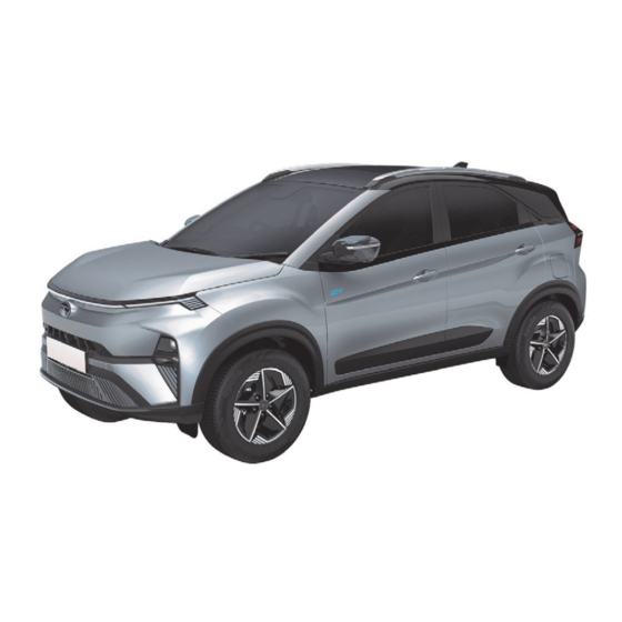
Page 14: Overview
INTRODUCTION TO EV OVERVIEW Know Your Vehicle 1. Bonnet 2. Turn Indicator/ DRL/ Position Lamp 3. Head Lamp 4. Fog Lamp 5. Front Parking Sensors 6. Front Camera 7. Front Windshield Wipers 8. Sunroof 9. Roof Rails 10. Windows 11. Rear View Mirror with Camera 12. - Page 15 INTRODUCTION TO EV 1. Charging flap 2. Position Lamp 3. Stop Lamp 4.Turn Indicator 5. Reverse Lamp 6. Reflex Reflector 7. Rear Parking Sensors 8. Tail Gate Open Switch 9. Rear Camera 10. High Mounted Stop Lamp 11.Rear Windshield Wiper 12.Shark Fin Antenna...
- Page 16 INTRODUCTION TO EV 1. Door Opening Lever 2. Door Opening Knob 3. Express Down 4. Power Window Switches 5. Inhibit Switch 6. Bonnet Opening Lever 7. Driver side Coin Box 8. Charging flap opening 9. Seat Ventilation 10. Seat 11. Regeneration Lever 12.
- Page 17 INTRODUCTION TO EV 1. Instrument Cluster 2. Horn 3. Driver Air Bag 4. Start/Stop Switch 5. Drive Modes 6. Gear Mode 7. Hazard Warning Switch 8. Infotainment Display 9. Passenger Airbag 10. Glove Box 11. Fascia Switches 12. Parking Brake 13.
- Page 18 INTRODUCTION TO EV Important Messages CAUTION In this Owner’s Manual, you will find the It indicates to be careful. You are capa- text under the heading “WARNING”, ble of doing something that might result “CAUTION” and “NOTE” which highlights in damage to equipment. important information.
-
Page 19: Safety
SAFETY IMPORTANT INFORMATION hicle, we recommend to kindly contact Safety Tips TATA MOTORS Authorized Service Safe Driving • Always take into account the road con- Centre. ditions, weather conditions, vehicle Safety consciousness not only ensures speed in order to prevent accidents. -
Page 20: Seats
SAFETY SEATS lock release lever. Sudden or unex- could thrown forward resulting in seri- Your vehicle is provided with good seating pected movement of the driver’s ous injury in the event of a sudden stop comfort. To make your journey more safe seat could cause to lose control of or collision. - Page 21 SAFETY Front Seat WARNING by pushing it forward and back- wards Do not drive the vehicle without the seat head restraints. Head restraints are in- CAUTION tended to help reduce injuries during an accident. Your hands might cut or injured by the sharp edges of the seats mechanism Rear Seat (If equipped) during looking for small objects trapped...
-
Page 22: Seat Belts
SAFETY SEAT BELTS tilt the tongue and pull on the lap seat Buckling The Seat Belt belt. A snug seat belt reduces the risk This section describes your Vehicle’s Seat of sliding under the seat belt in a colli- belts, Airbags and Child restraints system. sion. - Page 23 The seat is damaged, get it replaced immedi- belt will automatically retract to its stowed ately at TATA MOTORS position. If necessary, slide the tongue Authorized service centre. down the webbing to allow the seat belt to •...
- Page 24 SAFETY child (without child seat), system may Use of Seat Belts For Pregnant Seat Belt Warning Lamp detect occupancy and warn with seat Woman belt warning. It is not taken to mean WARNING child can occupy any passenger seat and use seat belt. Please refer CRS •...
- Page 25 SAFETY Seat Belts With Pre – Tensioner (if Seat Belt With Load Limiter (If equipped) equipped) You can use the pre-tensioner seat belts You can use the load limiter in the same in the same manner as ordinary seat manner as ordinary seat belts. The seat belts.
- Page 26 SAFETY Supplementary Restraint System (SRS - Airbags) There are 6 airbags provided in your car: Diver Airbag Front Passenger Airbag Side Airbag RH Side Airbag LH Curtain Airbag RH Curtain Airbag LH The driver airbag is mounted in the centre of the steering wheel.
- Page 27 SAFETY The ‘SRS’ system also comprises of the and occurs with considerable force, ac- NOTE following components depending upon the companied by loud noise and smoke, provided safety features in vehicle. which is normal. The inflated airbag, to- • Open your windows and doors as gether with seat belts, limit the movement soon as possible after collision to re- •...
- Page 28 SAFETY PAB switch is turned to ‘ON’ position. This occupant causing serious or fatal in- • Do not allow the front passenger to will ensure that the passenger airbag is juries. place their feet or legs on the dash- operational in the event of a collision. board.
- Page 29 SAFETY PAB Indicator ON: When switch is turned to ‘ON’ position to activate the airbag, ‘ON symbol & text’ will illuminate in amber color. PAB Indicator OFF: When switch is turned to ‘OFF’ position to deactivate the airbag, ‘OFF symbol & text’ will illuminate in amber color.
- Page 30 SAFETY Wrong Seating Positions...
- Page 31 We recommend the customer to imme- TORS Authorized Service Centre if place objects between the doors diately visit TATA MOTORS Authorized the vehicle is damaged, even if and passengers when they are Service Centre and get the SRS system...
- Page 32 We recommend the customer to imme- ated with the use of a rearward-facing This will lead to unexpected per- diately visit TATA MOTORS Authorized child restraint on front passenger seat dur- formance of system and may cause Service Centre and get the SRS system ing airbag deployment.
- Page 33 SAFETY from frontal airbags. Therefore, deploying airbags may deploy depending upon the WARNING frontal airbags in such situations will not severity of collision. In some of these con- Never use a rearward facing child re- protect the occupant. Head restraints and ditions, damage to the vehicle may be straint on a seat protected by an active minor or not be readily visible.
- Page 34 SAFETY Children On Board Child Restraint System (CRS) TATA MOTORS strongly recommends the WARNING use of Child Restraint Systems (CRS) for • Do not leave unattended children in all children up to 36 Kg and to be placed your vehicle.
- Page 35 Owner’s Man- ual as well as those provided by the child seat’s manufacturer. TATA MOTORS recommends Joie i- Spin Safe i-Size child seats for up to 18 Kg children. These seats are available at TML dealerships.
- Page 36 SAFETY ward or backward as per requirement, passenger is sitting at that position. Recommended CRS Position so that there could not be any contact • While installing child seats on rear out- between front passenger seat & child board seating position, adjust their re- seat or child present behind it.
- Page 37 SAFETY...
- Page 38 SAFETY Recommended CRS Position As Per The Vehicle Matrix Recommended CRS Positions (CRS Fastened With A Safety Belt) The suitability of seat position for carriage of children and recommended category of Front Passen- Front Pas- CRS is shown in the table as per the child Mass Rear Out- Rear Out-...
- Page 39 SAFETY CAUTION Recommended CRS Positions (CRS That Can Be Used With ISOFIX Sys- A CRS in a closed vehicle can become tem) very hot. To prevent burns, check the seating surface and buckles before Rear placing your child in CRS. Front Rear Grou...
- Page 40 WARNING seat belts, seats, ISOFIX and top-tether anchorages (as may be applicable) inves- If the airbag SRS warning indicator in tigated at TATA MOTORS Authorized the instrument cluster illuminates con- Service Centre. tinuously, it means that there is mal- function in the system. Remove the...
- Page 41 SAFETY Child Lock NOTE Lift the lock lever upward to deactivate the childproof lock when not required. Child lock are provided on both rear doors. It is used for safety of a child. Child safety lever to be used for safety of child for preventing them to open rear door while seating in passenger seat to avoid accident while vehicle is moving.
-
Page 42: Anti-Lock Braking System (Abs)
Drive carefully. Have ABS checked • However, remember that ABS will • You should therefore adapt your immediately at a TATA MOTORS not compensate for bad road or driving style to the different handling Authorized Service Centre as soon weather conditions or poor driver characteristics. - Page 43 SAFETY even surfaces like loose gravel, pot holes F. Electronic Brake Pre-fill (EBP) tre as soon as possible. by reducing the stopping distance com- The Electronic Brake Prefill (EBP) function pared to standard ABS. reduces the air gap of the brake pad and 3.
- Page 44 SAFETY celeration. The HFC function improve the brake intervention would mitigate • Panic brake alert warns surrounding stopping distance by eliminating required the effect of the subsequent collision vehicles when emergency or heavy pressure build-up lag by the driver. braking takes place. The function will •...
-
Page 45: Guideline For Preventing Fire And Electric Shock
Contact autho- as an implantable cardiac pace- feels hot during charging, unplug rised TATA MOTORS EV service maker in a person. When a person the gun and have a qualified electri- centre should you experience any... - Page 46 SAFETY moisture before using the charging gun. Never connect the charging gun to the mains with wet or moist hands or when the charging gun is wet. CAUTION • Do not use a damaged charging station, domestic plug point or charging port.
-
Page 47: Anti-Theft Device-Immobilizer/ Peps
NOTE Ignition ON Locked • Problem with Immobilizer system. Con- tact a TATA MOTORS Authorized Serv- Use only Flip key, the other should be ice Centre. kept in a safe location. Note down “key Contact a TATA MOTORS Authorized Serv- Tag no.”... -
Page 48: Battery And Component
TATA MOTORS EV service cen- Energy Information tre must be contacted for rectification. The vehicle battery pack has a maximum energy of 40.5kWh. - Page 49 30% out by TATA MOTORS after sales service only with registered entities (list of to 50% before leaving the vehicle for long...
-
Page 50: Tips To Conserve Battery Life
BATTERY AND COMPONENT TIPS TO CONSERVE BATTERY 2. Cell Balancing Or Equalization which can have impact on environment LIFE and are harmful if not handled/disposed Cell balanc- of carefully. There is a risk of severe 1. Battery Charging ing or equal- burns and electrical shock that may re- ization It is advisable to... - Page 51 BATTERY AND COMPONENT better to charge EV when ambient temper- ature is low especially at night. 4. Vehicle Parking Avoid parking vehicle in direct sunlight for long duration. Try to park it under shade, tree etc. This helps in keeping battery tem- perature low resulting enhance battery life over the life cycle.
-
Page 52: Charging
CHARGING INSTRUCTIONS TO FOLLOW Charging Box Socket Carefully read these instructions and the charging instructions before charging your electric vehicle. The Normal Charging gun is located inside the boot of the vehicle. As shown in the image, the parts for Nor- Charging system are: 1. - Page 53 Contact autho- the charging box is not in use to avoid • Change of vehicle state (Ignition OFF rised TATA MOTORS EV service misuse of charging point. to Ignition ON or vice-versa) should be...
- Page 54 CHARGING WARNING NOTE ical electric devices such as an im- plantable cardiac pacemaker in a per- Unplug both couplers of your Portable Charging station and domestic plug son. When a person has an implant like Charging Gun before cleaning. point must be approved/certified by a the one mentioned above, make sure to qualified electrician before using the ask the medical team and the manufac-...
-
Page 55: Important Tips
CHARGING IMPORTANT TIPS low voltage systems and prevents assistance. low voltage battery from getting • As EV service requires certain skillsets Do and Don’t discharged. and trained manpower, it is always rec- • Do not allow the vehicle to be dis- •... -
Page 56: Types Of Charging
CHARGING TYPES OF CHARGING Charging station to charge your car in a &hTab short duration. Charging Instructions Gun Unlocking Feature on EV Vehicle must be parked with park Once you switch off AC power supply, The brake in engage state before connect- charging gun will unlock after pressing ing the charging gun. - Page 57 CHARGING Here are the details of the different types of charging mechanisms: Types Of Charg- Charging Component Specifica- Charge Port Charge Gun Power Source tion • Nominal Voltage: 230V AC RMS Normal/AC Charg- single Phase 50Hz • Power Rating: 3.3Kw AC RMS •...
- Page 58 CHARGING ply. Normal / AC Charging Precautions For Normal Charging • In electricity grid, electric power is AC (alternating current) by nature. How- Proper maintenance of earthling pit is ever, electric power in battery is DC must. Add water & add salts at regular (Direct Current) by nature.
- Page 59 Charging Gun forcefully into the socket. It may damage the Charging Socket 8. If the actuator is engaged and the gun is not getting inserted properly, contact TATA MOTORS EV service center. 9. Remove any dust on the Charging...
- Page 60 CHARGING Gun and Charging Inlet. Connect the charging gun to vehicle AC Charging Inlet. Switch on the AC supply NOTE Charging Gun will be locked after When vehicle is in Charging Mode, it switching on the AC supply. You will will not go in Drive (D), Sport (S) or Re- hear a “click”...
- Page 61 CHARGING or partially engaged the charging won’t NOTE start and ‘Engage Park Brake to start charging’ message will be displayed on In emergency charging shutdown con- instrument cluster. ditions, Gun won’t be unlocked. Contact authorised TATA EV Service Centre. NOTE NOTE Infotainment and cabin cooling can be used during charging of the vehicle by...
- Page 62 CHARGING Normal Charging Control Box Indica- tions: Home Control Box Vehicle Fault...
- Page 63 CHARGING Control Working State Home Vehicle Fault Example Description Self-inspection Blink Blink Blink Blink Self-inspection for system state No fault Check for engagement of park brake Standby state Blink Plug temperature is high No fault Charging state Blink Blink Plug temperature is high No fault Charging stopped...
- Page 64 250V. Error in domestic supply side. “Stop Charging” Proper connection of plug and socket Blink Blink should be ensured. Also, check socket rating and use 15A socket Blink Control Contact TATA MOTORS EV Service fault Centre Blink Blink...
- Page 65 CHARGING Fault Cate- Control Indication Home Vehicle Fault Recommended Action gory Blink Go to nearest TATA MOTORS EV Vehicle box Service Centre Blink Blink Legend -Blink - Off - On...
- Page 66 CHARGING AC Charging (Wall Mount Unit) AC (WMU) Procedure This type of charging will help customer to APB should be in engaged condition improve the charging time for vehicle (Charging won’t start if APB is not en- charging. gaged). Approximately 6.5 hours (time for a 0- 100% charge, may increase basis factors such as ambient temperature, electrical load on meter, vehicle usage during and...
- Page 67 7. If the actuator is engaged and the gun is not getting inserted properly, contact TATA MOTORS EV service center. 8. Remove any dust on the Charging Gun and Charging Inlet. Connect the WMU charging gun to vehicle AC WMU Charging Inlet.
- Page 68 CHARGING Put on the protective caps on both NOTE bient temperature, the time required for Charging Gun and Vehicle Inlet. Place charging the high voltage battery may the Charging gun back and close the After a maximum of four fast charging vary.
- Page 69 CHARGING Remove any dust on the Charging Gun and Charging Inlet. Connect the charging gun to vehicle AC and DC Charging Inlet. Switch on the DC charging station sup- ply. Pull the ‘Charging-inlet Flap Open Normally the car starts automatically Lever’...
- Page 70 CHARGING In case the park brake is not engaged gun is plugged again. or partially engaged the charging won’t start and ‘Engage Park Brake to start NOTE charging’ message will be displayed on instrument cluster. In emergency charging shutdown con- ditions, Gun won’t be unlocked.
- Page 71 CHARGING State Of Charge (SoC) Gauge For High Voltage Battery Provided in the instrument cluster as a telltale. It shows the charging status of the high voltage battery. Low charge or minimum position on the indicator indicates that there is not enough energy in the high voltage battery. Full charge or max position indicates that the HV battery is fully charged.
- Page 72 Allow the charging port to dry completely. NOTE Water entering into the charging port will always be drained through the drain system. If water is stagnant in charging port area call Tata MOTORS Authorised EV service centre to rectify the issue.
- Page 73 CHARGING CPL while charging the vehicle S.n. Functions Charging Gun Cpl Condition Charging gun in Plug Charging sequence is displayed on vehicle (CPL). With animation running Charging state condition outwards progressively. Charging gun in Un- Charging sequence is displayed on vehicle (CPL) With animation running Discharging State Plug condition inwards progressively.
-
Page 74: Charging Do's And Don'ts
CHARGING CHARGING DO’S AND DON’TS ground and your hands are dry as well • Once charging is complete and gun is while using the high voltage charging removed from the charging port, it is • The charging gun provided for home equipment. -
Page 75: V2X Charging
CHARGING V2X CHARGING vehicle unlocks when the code on the • Since infotainment system won’t key matches with the code on the Battery be awake in Ignition OFF state, The V2X charging system offers a flexible Management System (BMS). In case of Limit can be set only in ignition ON and energy exchange method for charging PEPS variant, Immobilizer function is... - Page 76 CHARGING labels on the V2V gun and make sure hicle side, if there is no energy dissipa- fascia switch and then remove both the that the V2Vgun side labeled as tion has happened for 100secs from guns “source” should connect to the source successful step 7.
- Page 77 CHARGING Don’t press the V2X switch of sink ve- ther of the vehicles during the charg- beled as “source” should connect to hicle throughout the V2V function ing. the source vehicle & the other end la- beled as “sink” should connect to the Don’t keep the V2V charging gun open Do not insert the V2L connector when sink vehicle.
- Page 78 CHARGING level remove the gun from both side both. connecting the source side gun. After that both vehicle should brought If SOC of source vehicle reaches the Don’t perform V2V charging in other in to ignition OFF state. Keep the vehi- agreed Limit and to stop the V2V vehicles which is not recommended by cles in Ignition OFF state for 30sec.
- Page 79 CHARGING tion. • Discharge SOC Limit cannot be adaptor 3pin socket. Make sure that changed during the V2L function. Electrical loads are healthy/in good Vehicle To Load Charging (V2L) condition and ensure the relevant ca- • Incase if no limit is set by the user, bles and plugs of loads are connected 30% SOC will be consider as de- properly.
- Page 80 CHARGING step 4 to start 220V AC power supply disable the 220V AC power supply and posed to mud/metal particle etc). from vehicle. If user couldn’t press V2X Go to step 17. DON’TS switch within 120sec of step 3. Re- V2L function will automatically stops if Don’t crank the vehicle during V2L move the Gun completely and repeat...
- Page 81 CHARGING Don’t use the appliances if its cable V2L charging adaptor 3pin socket. sheath is damaged. Don’t mishandle the V2L adaptor. • Make sure that Electrical loads to Don’t use the electric devices which re- be used for V2L charging are Do not insert the V2L connector when quire continues power supply like med- healthy/in good condition and en-...
- Page 82 CHARGING quently when the V2L is in progress to • If the charging get interrupted after the use to ensure it is not ex- ensure there is no interruption/fault. again from vehicle side go to step posed to mud/metal particle etc. 14 to 15 and vehicle along with the To stop the V2L charging, first switch Don’t start V2L charging function if Ve-...
-
Page 83: Opening And Closing Keys
OPENING AND CLOSING KEYS • Do not leave the key in high temper- A key is an electronic access and authori- ature areas. The transponder in it zation system available as a standard fea- will behave abnormally when ture with your vehicle. reused. -
Page 84: Types Of Keys
OPENING AND CLOSING TYPES of KEYS Name Remote Key Description Locking all doors Approach light Smart Key (PEPS) Tail gate opening Unlocking all doors... - Page 85 OPENING AND CLOSING Smart Key (PEPS)(if equipped) nal indicators. If lock button is pressed on mechanical key blade, which is present the key with the any door open, locking- inside the smart key. unlocking takes place with audible warning indicators do not flash. Tail Gate Opening Approach Light Press the tail gate opening button once (3)
- Page 86 OPENING AND CLOSING Smart Key Features ing your vehicle. Smart Key Precautions Vehicle Search • For battery, replacement procedure If smart key is close to radio transmitter refer ‘MAINTENANCE’ section. such as radio station or an airport In vehicle locked condition, if lock button which can interfere with normal opera- on smart key is pressed, the turn indica- •...
-
Page 87: Doors
OPENING AND CLOSING DOORS Door Locking / Unlocking using Door Force Panic ON Operation Handle Switch (DHS) Option 1- Door Locking / Unlocking When vehicle is in OFF condition, if we press lock button and unlock button simul- with Key from Outside taneously, Force panic operation gets ac- tivated. - Page 88 OPENING AND CLOSING Locking / Unlocking The Doors From • Passive entry only works during ig- Inside nition off. Horn Honking when Door Locking using Door Handle Switch (DHS) If vehicle is in unlock condition and smart key is not available, (i.e. Smart Key is present away from authentication range) and if you try to lock the vehicle through door handle switch then vehicle horn...
-
Page 89: Windows
OPENING AND CLOSING WINDOWS When switch is pressed, red light turns NOTE ‘OFF’. The individual switches provided on Power Windows other doors are not functional. It can be Power windows can be operated for 30 seconds in ‘IGN OFF’ and ‘KEY OUT’ only operated by driver side switch. -
Page 90: Bonnet And Charging Flap
OPENING AND CLOSING BONNET AND CHARGING FLAP Individual Switches Bonnet Opening Individual switch has been provided on all doors. Make sure that the vehicle is in neutral and the parking brake is engaged. Pull the bonnet release lever. The bon- net will pop up slightly. - Page 91 For opening, open the charging flap, turn by one hand, disengage the stay rod TATA MOTORS Authorized EV Service the charging lever counter clockwise. and clamp it back properly. Centre only.
-
Page 92: Tail Gate Opening
OPENING AND CLOSING TAIL GATE OPENING Option Image Operation To release the tailgate, press the tail gate button on the remote. Option I Note: Tailgate can be unlatched without smart key. By Using Smart Key pressing tail gate button on smart key and pressing tail gate door, handle switch with 30 second. - Page 93 OPENING AND CLOSING WARNING NOTE • After unlatching, tailgate doesn’t get • During closing Tail gate if doors are opened automatically. in locked condition and valid smart • Tailgate should not be opened hold- key is inside the trunk, then Tail be ing tailgate garnish, this might dam- unlocked pressing...
- Page 94 OPENING AND CLOSING Emergency Tailgate Opening In case of electrical malfunction, you can unlock the tailgate from inside as per pro- cedure given below: Fold the rear seat to access the tail- gate opening knob. Open the knob cover. Pull out the knob to open the tailgate.
-
Page 95: Instrument Cluster Digital Display (7" Inch)(If Equipped)
INSTRUMENT CLUSTER DIGITAL DISPLAY (7” Inch)(If equipped) - Page 96 INSTRUMENT CLUSTER Gauge Name Information Note/warning • At every key IN and Ignition ON, the speedometer Bar moves to MAX and return to ‘0’ position. • This is welcome strategy and self-check feature The Speedometer Indicates the actual Speedometer • In vehicle running condition if the Speedometer is not vehicle speed in km/h showing the Vehicle speed, then take the vehicle to TATA...
- Page 97 INSTRUMENT CLUSTER Gauge Name Information Note/warning • For DRIVE mode, LED BARs will be ON as per the power consume in ECO & SPORT drive by taking instantaneous power consumption input. • For REGENERATION mode, LED BARs will be ON as per energy re- cuperation while driving by taking instantaneous power consumption input.
-
Page 98: Driver Information System (Dis)
This displays outside ambient temperature in units of °C with the reso- Outside Ambient lution of 1°C. Temperature Note: If display shows ‘- - ‘, take your car to TATA MOTORS Author- ized Service Centre. This feature monitors the Door Input and warns Driver if any Door is Door Ajar... - Page 99 Current Gear Indication Note: If is displayed, it means ‘Fault’ condition. In such case, take vehicle to authorized TATA MOTORS Authorized service Centre. The seatbelt warning indicator remains ON for 4 seconds, when igni- tion is turned ON. The warning lamp remains ON till all occupied seats belts are buckled.
- Page 100 INSTRUMENT CLUSTER Driver Information System Image Description “PRESS BRAKE” text warning comes ‘ON’ for 4 seconds when Press Brake BRAKE is not pressed to crank the vehicle. “SERVICE DUE” text warning comes ‘ON’ for 4 seconds when service Service due is overdue.
- Page 101 INSTRUMENT CLUSTER Driver Information System Image Description “HAPPY BIRTHDAY” text message comes ‘ON’ for 4 seconds Happy Birthday on owner’s birthday. (if equipped) HDC Active “HDC ACTIVE” text warning comes ‘ON’ for 4 seconds when hill de- (if equipped) scent control function is active. HDC deactivate “HDC DEACTIVE”...
- Page 102 INSTRUMENT CLUSTER Driver Information System Image Description This function displays the Charger Connected status information. When charger is not connected. Charger not connected When Charger is connected and not charging in IGN ON. When Charger is connected and charging ON in IGN ON. Charger Connected When charger is connected in IGN OFF.
- Page 103 INSTRUMENT CLUSTER Driver Information System Image Description This indicate the energy flow from the battery to the front wheels via electric motor or the flow to battery from high voltage components in case of regenerative braking. Animation = Forward (Battery to Motor) Energy Flow Animation and Energy Histogram Animation = Reverse (Motor to Battery)
- Page 104 Once 0.5 km distance is covered, Average Energy Economy shall be displayed. Even after 0.5 km distance covered for particular trip, Average Energy economy is displayed as ‘—-‘take vehicle to TATA MOTORS Author- ized Service Centre. Note: •...
- Page 105 INSTRUMENT CLUSTER Driver Information System Image Description Infotainment Informa- The instrument cluster will display information like media, navigation tion On Instrument and FM. Cluster Display Unit User can enter into setting screen by pressing select button while Settings Screen being in setting screen. Following screen gets displayed into setting screen: User can select Illumination Setting by Scroll down &...
- Page 106 INSTRUMENT CLUSTER Driver Information System Image Description Note: In the Setting menu if there is no user input for 10 secs the previous screen shall be displayed. Instrument Cluster equipped with digital clock which indicates current Clock time in 12 / 24 hours mode. SoC (State of Charge) gauge indicates the battery state of charge to State of Charge user in percentage.
- Page 107 INSTRUMENT CLUSTER Driver Information System Image Description Before you start the vehicle, press the brake pedal and then press the Press Brake Pedal start/stop button.
- Page 108 INSTRUMENT CLUSTER Driver Information System (DIS) Setting Operate the Up & down and Set Switch on steering wheel to see the Trip Info, Drive Assist, Vehicle Info, Notification, Navigation, Layout and Settings Window. Operate the Set Switch on steering wheel to reset TRIP A, AEE A, Average Speed A, Trip Time A (When TRIP A is displayed) and reset TRIP B, AFE B, Average Speed B and Trip Time B (When TRIP B is displayed).
- Page 109 INSTRUMENT CLUSTER Trip Information...
- Page 110 INSTRUMENT CLUSTER Drive Assist...
- Page 111 INSTRUMENT CLUSTER Vehicle Information...
- Page 112 INSTRUMENT CLUSTER Energy Analytics...
- Page 113 INSTRUMENT CLUSTER Notification...
- Page 114 INSTRUMENT CLUSTER Layout...
- Page 115 INSTRUMENT CLUSTER Setting Screen...
-
Page 116: Digital Display (10.25" Inch )
INSTRUMENT CLUSTER DIGITAL DISPLAY (10.25” Inch ) - Page 117 INSTRUMENT CLUSTER Gauge Information Note/Warning • At every key IN and Ignition ON, the speedome- ter Bar moves to MAX and return to ‘0’ position. The Speedometer Indicates the actual vehicle Speedometer speed in km/h • This is welcome strategy and self-check feature •...
- Page 118 OFF. Charge the vehicle • If there is any fault in the system, battery low warning symbol shall blink. Take your vehicle to the nearest TATA MOTORS authorized service station. • When driving on highways, make sure the bat- tery is charged enough...
- Page 119 Take your vehicle to Gauge or braking of the car. This energy is stored back in the nearest TATA MOTORS authorized service the battery for later use. There are 3 levels at the station. which energy recovery is done.
-
Page 120: Driver Information System (Dis)
This can Temperature cause an incorrect temperature reading when speed is under low speeds or when stopped. If display shows ‘- - ‘, take your car to TATA MOTORS Au- thorized Service Centre. - Page 121 DIS. Note: If is displayed, it means ‘Fault’ condition. In such Current Gear Indication case, take vehicle to authorized TATA MOTORS Authorized service Centre. The seatbelt warning indicator remains ON for 4 seconds, when ignition is turned ON. The warning lamp remains ON till all occupied seats belts are buckled.
- Page 122 INSTRUMENT CLUSTER Driver Information System Image Description “SERVICE DUE” text warning comes ‘ON’ for 4 seconds Service due when service is overdue. “LOW BRAKE FLUID” text warning comes ‘ON’ for 4 sec- Low brake fluid onds when brake fluid is low. “OVER SPEED”...
- Page 123 INSTRUMENT CLUSTER Driver Information System Image Description Happy Birthday “HAPPY BIRTHDAY” text warning comes ‘ON’ for 4 seconds (if equipped) on owner’s birthday. HDC Active “HDC ACTIVE” text warning comes ‘ON’ for 4 seconds (if equipped) when hill descent control function is active. HDC deactivate “HDC DEACTIVE”...
- Page 124 Even after 0.5 km distance covered for particular trip, Aver- Average Energy age Energy economy is displayed as ‘—-‘take vehicle to Economy for TATA MOTORS Authorized Service Centre. Trip A and Trip B Note: • AEE value is estimate of Energy economy. It may vary significantly based upon driving conditions, driving habits and condition of vehicle.
- Page 125 INSTRUMENT CLUSTER Driver Information System Image Description ‘RECHARGE’ shall be displayed which indicates that it’s the time to take your vehicle to the nearest charging station and the distance that a vehicle can travel with current charge is 20 Kms. Infotainment Information The instrument cluster will display information like media, On Instrument Cluster...
- Page 126 INSTRUMENT CLUSTER Driver Information System Image Description User can select Illumination Setting by Scroll down & press- ing Set Button in Setting Screen provided park lamp ON. User can increase the illumination from (20% to 100%) in 5 Illumination Setting steps by using UP &...
- Page 127 INSTRUMENT CLUSTER Driver Information System Image Description Set charging limit of the battery. The target charging level Charging Limits can be changed by 10%. Once the charging is completed as per set limit, the message is displayed Instrument Cluster equipped with digital clock which indi- Clock cates current time in 12 / 24 hours mode.
- Page 128 INSTRUMENT CLUSTER Driver Information System (DIS) Set- Setting Screen ting User can enter setting screen by pressing Cluster display screen can be controlled select button while being in setting screen. with the control button on the steering wheel. Only when the ignition switch is turned to ON can the instrument cluster be controlled.
- Page 129 INSTRUMENT CLUSTER Clock Setting 3. Digital Multiple Dial View Setting 1. Dial 1 view Settings Screen 2. Dial 2 view Settings Screen...
-
Page 130: Warning And Indicator
Lamp blinks: Vehicle is in immobilized condition when key is not inserted. Immobilizer (if Lamp ON: Problem with key/system. Contact a TATA MOTORS Authorized equipped) Service Centre. Lamp OFF: Normal condition (Authenticated user) and vehicle will start. - Page 131 This lamp comes on when ignition is switched ‘ON’ and goes ‘OFF’ in approx. 4 Airbag status seconds. If it continuously remains on or blinks then contact the TATA MOTORS Authorized service Centre immediately. Illuminates momentarily when ignition is switched ‘ON’. Once parking brake is Park Brake / Brake re-leased, it turns ‘OFF’.
- Page 132 Illuminates momentarily when ignition is switched ‘ON’. EPAS Amber Illuminates when there is a fault in the EPAS. Contact the TATA MOTORS Au- thorized Service Centre immediately. Seat belt warning indicator comes ‘ON’ for 4 seconds, when ignition is turned ‘ON’...
- Page 133 INSTRUMENT CLUSTER Warning Lamps Color Indicator Remarks Press Brake Pedal to Start This lamp comes on with IGN ON till user presses the Brake pedal to start Amber vehicle the vehicle. equipped) Daytime running lamps Green This lamp comes on when the Daytime Running lamp is ‘ON’. DRL (if equipped) Door Ajar lamp (if White /...
- Page 134 INSTRUMENT CLUSTER Warning Lamps Color Indicator Remarks When the vehicle speed crosses 80 kmph, then speed limit warning indicator turns ‘ON’ along with an audio chime for every two minutes (audible warning). When the vehicle speed is reduced below 75 kmph, then the speed limit warn- ing indicator and the audio warning will turn off.
- Page 135 Park Lamp Indicators used to display/Indicate the Position Lamp to Driver. This symbol is displayed when the vehicle is not getting charged even if the Charging Fail Indi- charger is connected. Contact the TATA MOTORS Authorized Service Centre to cator get the charging fail issue resolved...
- Page 136 This symbol lights up when the temperature of the battery is higher, and battery Battery High Tem- becomes hot. perature Contact the TATA MOTORS Authorized Service Centre if this indicator is getting on frequently. This symbol indicates the vehicle gone into limited performance mode. This usu- Limp Home Mode ally happens when the battery reaches 10% threshold or if there is any minor fault in power transmission or electrical components.
- Page 137 INSTRUMENT CLUSTER Warning Lamps Color Indicator Remarks Electronic Stability Illuminates momentarily when ignition is switched ‘ON’. Control (ESC) Amber If continuously ON then ESP system is at fault condition, Please take your vehi- (if equipped) cle to nearest TATA authorized service Centre at the earliest.
-
Page 138: Display Messages On Instrument Cluster
INSTRUMENT CLUSTER DISPLAY MESSAGES ON INSTRUMENT CLUSTER Warning Messages Warning / Information Title Warning Message Title Warning Message On Instrument Cluster Fasten Seat Belt - Driver Seat Belt Reminder Fasten Driver Seat Belt Speed Limit Warning Speed Limit Warning Over Speeding Detected Slow Down Drive Control Shift Denied Drive Mode Warning Drive Control Shift Denied... -
Page 139: Audio Reminders
INSTRUMENT CLUSTER AUDIO REMINDERS Feature Condition Reminder If you forget the key inside the vehicle Key-in Reminder /audio Warn- An audio warning will sound. Remove key to stop when you leave the ignition in ‘OFF’ posi - the warning. tion and door is open No key is detected in the vehi- An audio warning will be sounded for nine sec- If the vehicle is in ACC ON/IGN ON and... - Page 140 INSTRUMENT CLUSTER Feature Condition Reminder When user switches drive mode from city Sound warning for 1 second will be given to alert Drive mode chime to eco or city to sport (if equipped) user. Electronic Steering Column This feature informs the driver to rotate steering Lock (ESCL) chime wheel when ESCL gets engaged accidentally.
-
Page 141: Starting And Driving Driving Tips
STARTING AND DRIVING • Keep lights ‘ON’ if visibility is poor DRIVING TIPS the snow chain manufacturers. Driving on Wet Roads Night Driving Driving Through Water On wet road or during light showers, • Ensure that all lights are working and •... -
Page 142: Electric Power Assisted Steering (Epas)
STARTING AND DRIVING ELECTRIC POWER ASSISTED 40 – 60 kmph. Therefore they are ideal for sufficient distance between your vehicle city applications. Driving in this range and the vehicle ahead. STEERING (EPAS) along with following of other points here For long distance driving, perform safety Your vehicle is equipped with electric will add your mileage significantly. -
Page 143: Before You Start Ev
ISS button. • Position the seat and adjust the head- rests. • Contact the nearest TATA MOTORS Authorized Service Centre if in case • Adjust the inside and outside mirrors. of the above scenarios. •... - Page 144 STARTING AND DRIVING Procedure to Start EV engaged. tion, first press will bring the vehicle Release the parking brake and slowly With the smart key sit in the driver’s to Accessories On condition. Sec- release the brake pedal. See if the ve- seat (if equipped)/Engage the key in ond press will bring the vehicle to Ig- hicle slowly moves forward, then press...
- Page 145 STARTING AND DRIVING When the ‘Ready’ message is ON and if If the “—-” symbol is displayed, charge the Procedure to Stop EV the gear shifter is in a position other than vehicle immediately. After you charge your Hold down the brake pedal while the N (Neutral), the driver can accidently press vehicle, the distance to empty reading may vehicle is parked.
-
Page 146: Tips To Get Maximum Range While Driving Ev
STARTING AND DRIVING TIPS TO GET MAXIMUM RANGE • Gradually press and release the accel- Freeing A Frozen Door Lock erator pedal when accelerating or de- WHILE DRIVING EV To prevent a door lock from freezing, apply celerating. • If safe to do so, modulate the acceler- anti-icing agent through the key hole. - Page 147 STARTING AND DRIVING accelerator pedal position in the D Regenerative Braking and generates power for the high volt- (Drive) position. age battery. • This vehicle is • Drive at a constant speed. Maintain • Power is also generated when the equipped with a cruising speeds with constant acceler- brake pedal is applied.
- Page 148 STARTING AND DRIVING • Regenerative brake is also automati- 24-26 deg C. Vehicle is equipped with pace, in between 40-80 km/hr will help an cally reduced when the battery temper- Remote Air conditioning. You can remotely electric car to maximize range. Predictive ature is high/low to prevent battery start Air Conditioning system.
- Page 149 STARTING AND DRIVING Unauthorized Electrical Accessories Unauthorized aftermar- electrical acces- sories can potentially consume higher energy than factory fitted ones and may affect range di- rectly. They can also lead to functional complications and lower component life in the long run. It is recom- mended to fit only TATA Genuine Acces- sories at Authorized EV Service stations.
- Page 150 STARTING AND DRIVING Limp Home Strategy Soc InTervention Zone IPC message and state Max speed Acceleration Grade ability Cabin cooling If the vehicle is in Sport mode, it will automatically shift to Drive SoC <=25% No change No change No change mode which will be shown on clus- Then SoC Gauge 1 Bar ON with...
-
Page 151: Drive And Gear Modes
STARTING AND DRIVING DRIVE AND GEAR MODES Limp Home Condition of EV Limp Home Mode Telltale Warnings In situations when certain conditions in the Drive Modes vehicle are not met or when some fault HV Critical Fault arises in the vehicle, the vehicle control Contact TATA unit intervenes and puts the vehicle into... - Page 152 STARTING AND DRIVING Gear Modes Neutral (N) Drive Performance Mode The Vehicle is in Neutral gear position and ‘N’ will be indicated in Instrument Cluster. Increased Motor Torque and CITY Power output for BALANCED Drive Mode (D) performance. Vehicle moves forward and ‘D’ will be indi- Optimum Motor Torque and cated in Instrument Cluster.
- Page 153 STARTING AND DRIVING Mono-stable Shifter • Your vehicle is equipped with Mono stable shifter, where the shift lever re- turns to its stable position the moment it is released. • It is provided with 2 UP positions and 2 DOWN positions: UP2-UP1-Stable- DOWN1-DOWN2.
-
Page 154: Operating Of Lights And Wipers
STARTING AND DRIVING OPERATING LIGHTS Auto Light 3. High Beam WIPERS Move the lever forward to select the high beam function. Pull the lever back to nor- Combi-switch (RH Stalk) mal for low beam. The headlights will be automatically 4. High Beam Flash (Spring Return) switched ON depending on ambient light conditions (while entering a tunnel or when To flash the high beam, pull the lever to-... - Page 155 STARTING AND DRIVING Head Lamp Leveling Rotary Switch Combi-switch (LH Stalk) 2. Slow Wipe Push the stalk towards position (2) for con- tinuous slow wipe. 3. Fast Wipe Push the stalk towards position (3) for con- tinuous slow wipe. 4. Flick Wipe (Spring Return) Pull the stalk downwards and hold it for continuous wipe, the wiper continuously wipes...
- Page 156 STARTING AND DRIVING Horn Manual Mode Rear Wash and Wipe • Pull the lever little longer, to spray the washer fluid on the windshield. • The windshield wipers will operate for three cycles after the lever is released and for one more cycle after five sec- onds.
-
Page 157: Seats Adjustments
STARTING AND DRIVING SEATS ADJUSTMENTS WARNING ous. First Row Seats Adjustments You could slide under the seat belt in a Do not adjust the driver’s seat while collision. Manual Adjustments driving. Adjusting the seat while driving could cause the driver to lose control of 2. - Page 158 STARTING AND DRIVING 1. Co-Driver seat Backrest Angle Ad- Power Seats Adjustments justment Drive Power Seats Adjustments Similar to driver seat, to change the seat back rest angle, lean forward slightly and pull up the lever (1). Adjust seat backrest until it reaches desired comfortable posi- tion.
- Page 159 STARTING AND DRIVING lever returns to its original position and Co-Driver forward / backward Co-driver Power Seats Adjustments seat is securely latched. adjust-ment NOTE Lift lever (2) and slide the seat forwards rearwards. Release lever Adjust the seat backrest until your arms make sure that seat is securely latched are slightly angled when holding the steering wheel.
- Page 160 STARTING AND DRIVING Seat Ventilation To protect ventilated seats- To start ventilation, press button once. • Use the air ventilation seat ONLY when the vehicle HVAC system is on. • Never use a liquids like alcohol, high viscosity oils or other to spill on venti- NOTE lated seats.
- Page 161 STARTING AND DRIVING • Fold the backseat as shown in the fig- Rear Seat Adjustments ure. Rear Seats Folding (60-40%) Equipped) You can increase the luggage capacity by folding the respective rear seats as re- quired. • Lift the seat as shown in the figure. NOTE •...
- Page 162 STARTING AND DRIVING Rear Seats Folding (100%) (If equipped) You can increase the trunk capacity by folding the rear seat. For folding: • Pull the backrest release knob pro- vided on both side simultaneously. • Fold the backseat as shown in the fig- ure.
-
Page 163: Mirror
STARTING AND DRIVING MIRROR WARNING NOTE Inside Rear View Mirrors (IRVM) • You should always engage the rear Use antiglare position only when neces- seat if you do not need the through sary, as it reduces rear view clarity. loading feature. •... - Page 164 STARTING AND DRIVING function. Outer Rear View Mirror (ORVM) To adjust the Mirror The LED indicator on the IRVM shows the Motorized ORVM Adjustment active status of auto dimming function. equipped) The auto dimming IRVM is defaults to the ON position whenever the ignition switch is turned ON and it is switched OFF when- ever reverse gear is engaged.
- Page 165 STARTING AND DRIVING ORVM Folding Option 2: Auto folding by Smart Key Option 3: Auto Folding by Knob Option 1: Manual Folding ORVMs can be folded or unfolded manu- ally. This is applicable only for vehicles which are not equipped with motorized folding provision.
-
Page 166: Driving Support System
STARTING AND DRIVING DRIVING SUPPORT SYSTEM and parking brake warning lamp is OFF • Use wheel chocks if the vehicle is parked on a slope. before start of the drive. Park brake Automatic Parking Break warning lamp in cluster at vehicle running NOTE Mechanical parking brake acting on the condition indicates failure in brake system... - Page 167 STARTING AND DRIVING Surround View System (SVS) Surround view system displays the sur- roundings around the vehicle to the driver for safe and comfortable drive. SVS assists the driver while reversing and maneuvering the vehicle at lower speeds. Camera Locations As Shown In The Im- ages Left Side Camera Rear Camera...
- Page 168 STARTING AND DRIVING The shift lever is in D (Drive), N (Neu- Activation Of SVS Deactivation Of SVS tral) or R (Reverse) and vehicle speed The function is activated when: SVS function is deactivated when one of is under 17 kmph and surround view the following step is performed.
- Page 169 STARTING AND DRIVING Surround View System Features The Surround view system has the follow- ing features 2D View 3D View 2D Top + Front view 2D Top + Left view Front Corner View Rear Corner View Full View Settings Cancel Icon 2D View 2D Top + Right view By selecting 2D Icon which is available on...
- Page 170 STARTING AND DRIVING 3D View By selecting 3D Icon, cameras provide about 360 degree 3D view of vehicle’s sur- rounding on the Infotainment screen In 3D mode view 8 camera icons will be Fig 3. Front corner view Fig 4. Rear corner view present around the model car image to switch to different angle of view.
- Page 171 STARTING AND DRIVING II. 2D Full Rear view Settings By selecting 2D rear view Icon which is • By selecting the settings icon available available on the model car image, cam- on the infotainment screen, driver can eras provides about wide 2D view of vehi- change the settings as required.
- Page 172 STARTING AND DRIVING Understanding Guidelines Indication Static Guidelines SVS rear view default mode settings Yellow Line Cancel Icon Indicates, if rear objects are in this colored zone, you have to take utmost care. How- By selecting the cancel icon which is avail- Dynamic Guidelines ever, objects fall in this zone, may not hit able on the top right corner of the infotain-...
- Page 173 STARTING AND DRIVING speed. We can enable/disable the blind view monitor in HMI settings based on the user choice. In driver assistance system will provide many other options in that user should se- PDC Guidelines Settings lect the park assist delay timer. System will User can change the timer settings for provide three different option such as PDC guidelines which is available on the...
- Page 174 STARTING AND DRIVING • On activating the left turn indicator, left Green Line: Indicates, if rear object is be- open. If tailgate is open, visual infor- side rear view should be displayed on hind this colored line, you have to be cau- mation may not be the actual rear view infotainment along with the static over- tious.
- Page 175 STARTING AND DRIVING not provide you the visual image and line or volatile organic solvents (gaso- • Do not apply any kind of force on may damage camera. line, acetone etc). This may damage the camera. the camera lens • Do not add any accessory, which will •...
- Page 176 STARTING AND DRIVING Understanding Guidelines Indication WARNING SVS system is an aid only. User need to check surrounding for safety. Rear View Camera Static guidelines Activation Reverse gear This system will start, if reverse gear is en- gaged, or park assist button (if equipped) is pressed or manual activation is done through Infotainment screen.
- Page 177 STARTING AND DRIVING You have to take utmost care if objects fall cause blockage to the camera’s field of era lens using stick or hard material. in this zone. However, the objects may not view. Use normal water and soft cloth. hit vehicle.
- Page 178 STARTING AND DRIVING or below the bumper, underneath • In case of uneven road conditions or the vehicle, or objects out of the up-hill or downhill conditions, do not camera’s field of view. The area dis- depend on rear view camera park played on the screen may vary ac- aid.
- Page 179 STARTING AND DRIVING When sharp up gradient behind the The distance guidelines will appear to be closer to the vehicle than the actual dis- vehicle tance. Because of this, objects will appear to be farther away than they actually are. In the same way, there will be a margin of error between the guidelines and the ac- tual distance/course on the road.
- Page 180 STARTING AND DRIVING When any part of the vehicle sags (such as vehicles) using the distance guidelines. When approaching a three-di- mensional object. Distance guidelines Visually check the surroundings and the area behind the vehicle. On the screen, it When any part of the vehicle sags due to appears that a truck is parked at point B.
- Page 181 STARTING AND DRIVING Visually check the surroundings and the Vehicle width guidelines Front Park Assist System area behind the vehicle. In the case shown below, the truck appears to be outside of the vehicle width guidelines and the vehi- cle does not look as if it hits the truck. However, the rear body of the truck may actually cross over the vehicle width guidelines.
- Page 182 STARTING AND DRIVING if user has turned ON Low speed acti- by selecting this feature in Infotainment Deactivation vation from user settings menu. When- display to see any obstacle behind the ve- System will stop, if reverse gear is disen- ever vehicle speed is below 10kmph hicle while parking.
- Page 183 STARTING AND DRIVING safely. Park Assist Indications WARNING Reverse Park Assist feature works on ultra In case reverse park assist system mal- 0 to 25 cm obstacle detection perform- sound echo technology, due to which per- functions, fault message may appear on ance is not guaranteed due to ultrasonic formance is not guaranteed in following the infotainment screen.
- Page 184 STARTING AND DRIVING • If the sensor areas are extremely hot General Warning position, contact your dealer for refit- from direct sunlight or cold due to In low light conditions, the screen may ment. freezing weather. darken or image may appear faint. •...
-
Page 185: Automatic Vehicle Hold (If Equipped)
STARTING AND DRIVING AUTOMATIC VEHICLE HOLD (if door is closed. AVH indication and warning lamps which equipped) will appear on the cluster is provided Press AVH switch. below. Auto Hold indication turns on in the Cluster which indicates AVH is turned ON and in Standby mode. - Page 186 STARTING AND DRIVING switch input from user. Precautions During Vehicle Towing WARNING with APB NOTE If any abnormality is present in the sys- Before towing please ensure APB is not tem, AVH malfunction lamp in amber Auto hold function will not become ac- engaged as it can damage Brake pads colour will glow which is amber in tive if...
- Page 187 Compo- nents permanently. WARNING DO NOT jump start the vehicle, since it is an EV. If the 12V battery is completely discharged, contact the nearest TATA MOTORS EV service center.
-
Page 188: Interior Features
INTERIOR FEATURES CLIMATE CONTROL Air Distribution The Climate Control regulates the temperature inside the vehicle and filter the dust particles in cabin based on the user set temperature settings. The air is distributed through the vents in the passenger compartment as shown below:... - Page 189 INTERIOR FEATURES Air Vents Rear Ac Vent Dashboard Side And Front Centre Vent Rear AC vents are available between two front seats. It can be switched ‘ON’ pro- Air vents are available on the dashboard. vided that front AC is switched ‘ON’. The direction of air flow can be adjusted using sliders on the respective vents.
-
Page 190: Fully Automatic Temperature Control Fact) (If Equipped)
INTERIOR FEATURES FULLY AUTOMATIC TEMPERA- Fresh air / recirculation Also, when the display is not in climate mode then climate information will be dis- TURE CONTROL (FATC) Air distribution (mode) played on the all-time display available on equipped) OFF mode the top bar and widget. - Page 191 INTERIOR FEATURES windscreen for faster defrosting. (It When the recirculation switch is ulate the mode automatically. However, also overrides any mode selection you turned ON, air from the vehicle’s inte- user override is possible with the use of may have made). rior is sent throughout the system.
- Page 192 INTERIOR FEATURES lower limit (Lo) or its upper limit (Hi), Off Mode Temperature Control Knob the system runs at full cooling or heat- ing only. It does not regulate the inte- rior temperature. NOTE Select the OFF switch to turn the system Move the temperature control toggle In ‘AUTO’...
- Page 193 INTERIOR FEATURES Also, if required, the driver window will roll Outside Ambient Temperature (OAT) NOTE down to flush the hot air from inside the Sensor cabin. Once cabin has been sufficiently The Xpress Cool function can only be Outside Ambient Temperature (OAT) sen- flushed, the system will announce to take turned ON if the Ambient temperature is sor located under the front bumper grill.
-
Page 194: Cabin Air Purification
INTERIOR FEATURES CABIN AIR PURIFICATION FASCIA SWITCHES Air Quality Index : (If equipped) The Climate Control System fitted with ad- • Climate control system fitted with vance filter for cabin air purification. FATC calculates Air Quality Index (AQI) of cabin using PM2.5 AQI Index. •... -
Page 195: Power Sunroof
INTERIOR FEATURES POWER SUNROOF 2 inlet during the charging process. Charg- other road users to see you. It turns to ‘ON’ ing gun unlock switch is used to unlock the when the fog lamp switch is turned on It bring natural light and fresh air into pas- actuator present in CCS type 2 inlet to when the ignition is ‘ON’... - Page 196 INTERIOR FEATURES Manual Switch two detents. Sunshade Close Position • 1st detent Manual (long press) to close and stop at desired position. • 2nd detent Express (one touch) to close Sunroof completely. Press at the center of the knob for tilt up/down function.
- Page 197 INTERIOR FEATURES • Give the “sunroof open/close” com- • Ensure that there is no noise distur- mand. Sunroof will be opened/closed. bance when you speak the commands like, other passengers in the vehicle are talking or there is lot of wind noise. Disturbance from external sound sources may result in poor voice recognition.
- Page 198 • Rain Detection: When sunroof is open MOTORS dealer or an authorized below: and rain is detected (based on Wiper TATA MOTORS Service Facility for speed is slow/high upon raining), then On the 4 attempt continuously press assistance. Sunroof will close automatically...
- Page 199 INTERIOR FEATURES juries or vehicle damage. Automatic Reversal / Anti-pinch Func- WARNING tion Never deliberately use your body parts to Never try pinching of any part of your test the automatic reversal function. The body intentionally to activate the Auto- sunroof glass may reverse direction, but matic reversal function.
- Page 200 ‘sunroof close switch’ and keep the switch pressed for 1-2 seconds after 1. B-Call Switch: I-Call will connect you the roof is fully closed, till clicking to TATA MOTORS Roadside sound comes from Sunroof. assistance for Towing. Not for The Initializing command is complete, ambulance service.
-
Page 201: Steering Mounted Controls (If Equipped)
INTERIOR FEATURES STEERING MOUNTED CONTROLS source in the infotainment system i.e. 6. Phone Reject USB, AM, FM and Bluetooth. (if equipped) Press the switch to reject or hang up a Steering Mounted Controls (LHS) phone call. NOTE 7. Mute For more information, refer infotainment Press the switch to mute a phone call / manual. - Page 202 INTERIOR FEATURES 2. Pagination 7. Selection (OK) • Default regeneration level on the ve- hicle when vehicle is cranked will be Press the switch to enter in to cluster Push the OK button to access/select the Level 1. screen. submenu screens of a main menu item. Regeneration Switch Default Regener- 3.
-
Page 203: Infotainment System Display
INTERIOR FEATURES INFOTAINMENT SYSTEM DISPLAY Option III Option II Option I... -
Page 204: Mic (If Equipped)
INTERIOR FEATURES MIC (if equipped) change button (long Press) for more Master /force Restart Process than 10 sec) and release as soon as If your infotainment system touch screen display’s goes blank becomes unresponsive or shows some unusual behavior, then you can restart it to NOTE potentially resolve the issue. -
Page 205: Speakers & Tweeter (If Equipped)
INTERIOR FEATURES SPEAKERS & TWEETER USB Port(if equipped) equipped) Front USB A + C Charger Speakers and Tweeters are available in models with infotainment system. Provi- sions are given for music system and speakers on versions without infotainment A type USB port is used to connect your system. -
Page 206: Power Socket
INTERIOR FEATURES POWER SOCKET Rear USB A + C Charger Behind Rear Seat On LH Side On Center Console Connect to fast charger your device like The power socket will work when the igni- smartphone/Tablets/Laptop/iPhone /iPad tion switch is in the “ACC” or “ON” position. This socket can be used to provide 12V (10A) power for electrical accessories. -
Page 207: Antenna
INTERIOR FEATURES ANTENNA LAMPS b) DOOR Roof Lamp Interior roof lighting lamp is provided on the roof with inbuilt switch. In this position the lamp turns to ‘ON’ when either of the doors are opened. When the last door is closed, the lamp will turn ‘OFF’ with dimming. -
Page 208: Head Lamp And Tail Lamp
INTERIOR FEATURES HEAD LAMP AND TAIL LAMP Boot Lamp Tail Lamp Head Lamp Position Lamp Turn Indicator / DRL / PO Turn Indicator Head lamp (High / Low beam) Tail/stop Lamp Fog lamp Reverse Lamp Reflex Reflector High Mounted Stop Lamp... - Page 209 INTERIOR FEATURES Logic Of Lamps Vehicle Condi- Position Functions FDI On Remark tion Lamp LH & RH DRL activate in day Ignition On time only with high intensity Rotate stalk to turn LH,RH DRL & CPL “ON” dur- Position ‘ON’ the Parking ing night condition with low in- lamps.
- Page 210 INTERIOR FEATURES Welcome And Good Bye Strategy Vehicle Key Condi- S.n. Function Cpl State On Vehicle Remark Condition tion FDI Blink one time & Ani- mation start from vehicle Welcome Ani- Unlock key Unlock center to outboard side. mation on Pressed Total time for animation is approx 3.5 Sec.
-
Page 211: Roof Grab Handle
INTERIOR FEATURES ROOF GRAB HANDLE VEHICLE TELEMATICS Event based recording Car is equipped with iRA - Connected car This includes data generated during spe- Technology which offers a host of features cific events like vehicle collision, intrusion, to the users through the “iRA - Connected un-authorized entry etc. -
Page 212: Wireless Power Charging (If Equipped)
INTERIOR FEATURES WIRELESS POWER CHARGING (IF Location of Wireless Charger TATA MOTORS does not disclose the data EQUIPPED) recorded from your vehicle to any third Location: The location of the WPC in ve- party except: hicle is in the Centre console area as WPC System Description below. - Page 213 Functions of WPC System not resolved you are advised to visit A. Charging function: Charge smart WPC system detects the presence of the TATA MOTORS Authorized Service phone phone and starts charging as per the Qi Centre. Following all the conditions are applicable standard protocol.
- Page 214 INTERIOR FEATURES INFORMATION Do’s and Don’ts • The wireless charging function is sup- WARNING ported to charge smart phones which 1. If any metal object such as coin is lo- are Qi compatible. Certain features cated between wireless charging pad may not function as not supported by and phone back, the charging may get the smart phone manufacturer and not...
- Page 215 INTERIOR FEATURES Wireless charger works on principle of Do not place smart phone up-side Information magnetic induction, i.e. it converts down on charging pad or do not miss Small noise may be heard when a electrical energy into magnetic energy aligned mobile phone on charging pad smart phone which does not support in such case smartphone charging will...
- Page 216 INTERIOR FEATURES After the mobile phone temperature large display, airport, or other facility stays ON until the phone is fully charged. drops below threshold, the wireless that generates strong radio waves or charging function will resume. Mobile electrical noise. temperature cut off threshold is much WPC ECU in Standby Mode lower than WPC temperature cut off The infotainment system displays no...
- Page 217 INTERIOR FEATURES Metal Object Detection Mode Smart Phone Battery is Full/ Charg- NOTE ing Completed The charging gets interrupted/stopped due • Delay in restarting of mobile charg- to metal object placed on the charging The smart phone fully charged status is in- ing will be observed if foreign ob- pad.
- Page 218 INTERIOR FEATURES WPC System Error Mode NOTE The error in the WPCF wireless power If error message is pop up on head unit charger with FAN, system may cause the then avoid charging the smart phone error message to get displayed on the in- and visit the nearby service station.
-
Page 219: Stowage Area Storage Compartment
STOWAGE AREA STORAGE COMPARTMENT Glove box Driver side coin box Utility pockets on front doors Utility pockets on rear doors Luggage Compartment Foldable arm rest/ Cup holder... -
Page 220: Glove Box
STOWAGE AREA GLOVE BOX Cup holder NOTE Receipts etc. Make sure that glove box flap is closed Cooling Facility (if equipped) while driving. Stowage Detail Opening And Closing To open- Press the knob and open the glove box flap. On selected models glove box is provided with a cooling facility. -
Page 221: Driver Side Coin Box
STOWAGE AREA DRIVER SIDE COIN BOX UTILITY POCKETS on FRONT UTILITY POCKETS REAR DOORS DOORS Stowage is provided on RH side of steer- ing wheel for Coin, mobile and wallet. Utility pockets are provided on front doors Utility pockets are available on rear doors and it can be used to keep following items. -
Page 222: Center Console
STOWAGE AREA CENTER CONSOLE FOLDABLE REST equipped) Stowage Below Arm Rest A foldable arm rest has been provided in the rear seat. It also has two-cup holders, which can be accessed by opening the cover. When not required, fold the armrest back into the seat. -
Page 223: Luggage Compartment
It can be used to keep small items. NOTE TATA MOTORS does not recommend use of any floor mats below driver foot, Store the luggage in luggage compart- from occupant safety point of view. If ment. - Page 224 STOWAGE AREA Hook For Purse Holder Collapsible Hook Carrier Hook In Luggage Compart- ment Collapsible hook is provided for hanging small carry bags etc. Carrier hook is provided for hanging small carry bags etc. Load up to 3 kg is permis- sible.
-
Page 225: Luggage Compartment Cover
STOWAGE AREA LUGGAGE COMPARTMENT ROOF RAIL COVER Aesthetic Roof Rail Luggage cover is designed only for hiding NOTE the luggage compartment. Do not apply load or mount roof rack on NOTE roof rails. Do not place anything on luggage cover as it could obstruct driver’s rear view. -
Page 226: Emergency And Breakdown
EMERGENCY AND BREAKDOWN EMERGENCY EQUIPMENT Tool Kit, Tow Hook, Jack And Spare structions in this section before attempt- Wheel You should be familiar with the location of ing to use the jack. the emergency equipment provided in the Following parts are provided in the Bag as vehicle and how to use it. -
Page 227: Spare Wheel Removal Process
EMERGENCY AND BREAKDOWN SPARE WHEEL REMOVAL blink. Keep the warning triangle at an ap- proximate distance of 50-150 m behind PROCESS your vehicle in the same lane of traffic. The • To access the spare wheel, lift the car- reflecting side of the triangle should face pet up. -
Page 228: In Case Of Flat Tyre
EMERGENCY AND BREAKDOWN IN CASE of FLAT TYRE • Switch off the IGN. Changing Flat Tyre • Keep advance warning triangle at a • Reduce vehicle speed gradually, Avoid Loosen the nuts (as indicated) on the suitable distance behind the vehicle as sudden steering movement or braking. - Page 229 EMERGENCY AND BREAKDOWN Jack Up Point Location On Vehicle • Do not open or close a door or the NOTE tailgate when the vehicle is raised. • The jack is designed only to raise and hold the vehicle for a short time Assemble the Jack handle and wheel while a wheel is being changed.
-
Page 230: Puncture Repair Kit Option 1 (If Equipped)
EMERGENCY AND BREAKDOWN PUNCTURE REPAIR KIT OPTION 1 Remove wheel nuts with the help of wheel NOTE spanner and take out flat tyre. (if equipped) • Do a check and correct the tyre Introduction NOTE pressure and wheel nuts tightness of the changed wheel at nearest au- Do not place wheel nuts in sand or on a WARNING... - Page 231 EMERGENCY AND BREAKDOWN tire damage, some tires can only be ture repair Kit without being in danger. WARNING partially sealed or not sealed at all. • Engage the hand brake, even if you Do not use the Puncture repair Kit if the •...
- Page 232 EMERGENCY AND BREAKDOWN Location In Vehicle Puncture Repair Removal Process Remove the two Velcro as shown in figure and take out the puncture repair kit. In Luggage compartment...
- Page 233 EMERGENCY AND BREAKDOWN Steps &hTab...
- Page 234 EMERGENCY AND BREAKDOWN How To Proceed In The Event Of A may rise up to 500 KPa (5 bar. 73 psi) Step 1 but will drop again after about 30 sec- Tire Puncture Take out the hose and power plug with onds First pump the tire sealant and air into the cable out of the tyre puncture repair kit...
- Page 235 EMERGENCY AND BREAKDOWN Step 2 Stop the vehicle after driving about 3- WARNING 10 km. Check and where necessary, Once a tyre inflation pressure of at Check the sidewall of the tyre prior to in- adjust the pressure of the damaged least 180kPa (1.8 bar/26 psi) has been flation.
- Page 236 EMERGENCY AND BREAKDOWN tyre valve cap and put back on the pro- and screw the inflator hose into the tire WARNING tective cap of the hose. valve After using the sealant you may drive Leave the bottle in the holder and store •...
-
Page 237: Puncture Repair Kit Option 2 (If Equipped)
EMERGENCY AND BREAKDOWN PUNCTURE REPAIR KIT OPTION 2 tire damage, some tires can only be NOTE partially sealed or not sealed at all. (if equipped) New sealant and replacement parts can • Loss of tire pressure can affect vehicle Introduction be purchased from your authorized re- handling and vehicle control. - Page 238 EMERGENCY AND BREAKDOWN ture repair Kit without being in danger. Location In Vehicle WARNING • Engage the hand brake, even if you Do not use the Puncture repair Kit if the have parked on a level road, to ensure tire has already been damaged as a re- that the vehicle will not move.
- Page 239 EMERGENCY AND BREAKDOWN Puncture Repair Removal Process Remove the two Velcro as shown in figure and take out the puncture repair kit.
- Page 240 EMERGENCY AND BREAKDOWN Steps &hTab...
- Page 241 EMERGENCY AND BREAKDOWN Step 1 may rise up to 500 KPa (5 bar. 73 psi) WARNING but will drop again after about 30 sec- Take out the hose and power plug with onds Ensure pump should not be ON for cable out of the puncture repair kit cas- more than 10 min as it may heat up and Inflate the tyre to an inflation pressure...
- Page 242 EMERGENCY AND BREAKDOWN Start and drive for about 3-10 km so Once you have inflated the tyre to its WARNING that the sealant can seal the damaged correct tyre pressure, switch off the Need to drain fluid from tyre before re- area.
- Page 243 EMERGENCY AND BREAKDOWN power socket and assemble it properly bumps or similar damage on the side and keep the unit in luggage space wall, do not continue to use the tyre. again for next use. NOTE WARNING • Remove the puncture repair kit from After using the sealant you may drive Remember that emergency road-side the luggage area.
-
Page 244: Towing
• Fasten the tow rope or tow bar at damage to your vehicle, take help of a the towing eyes. Otherwise, the ve- TATA MOTORS authorized dealer or a hicle could be damaged. commercial tow-truck service. • When towing, pull away slowly and •... -
Page 245: Fuses
EMERGENCY AND BREAKDOWN FUSES Recommended Towing In case of break down, we recommend Your vehicle has fuse boxes at three loca- that your vehicle be towed with the driving tions. wheels off the ground or place the vehicle The vehicles electrical circuits have fuses on a flatbed truck as shown. - Page 246 In the fuse box, identify the defective • If a newly inserted fuse also blows, fuse from its melted wire. have the cause traced and rectified at nearest TATA MOTORS Authorized Dealer/Service Center immediately. WARNING • If you manipulate or bridge a faulty...
- Page 247 EMERGENCY AND BREAKDOWN WARNING If fuse box cover is removed for any reason, it should be refitted properly in its original position. Motor Compartment Fuse Box NOTE The fuse box layout is for reference pur- pose only. Please refer the sticker pro- vided inside the fuse box cover.
- Page 248 EMERGENCY AND BREAKDOWN Fuses - Motor Compartment Note: Please refer fuse box sticker on vehicle for more clarity.
- Page 249 EMERGENCY AND BREAKDOWN Under Bonnet Fuse Details Fuse No. Ratings (AMP) Fuse Type Description JCASE SUPPLY CABIN FUSE BOX-1 JCASE IVBAC ECU JCASE IVBA MOTOR JCASE COOLING FAN FAST JCASE EV POWERTRAIN JCASE COOLING FAN SLOW JCASE SUPPLY CABIN FUSE BOX-2 JCASE SPARE JCASE...
- Page 250 EMERGENCY AND BREAKDOWN Under Bonnet Fuse Details Fuse No. Ratings (AMP) Fuse Type Description EF21 MINI BRAKE SW EF22 MINI HV BATTERY COOLING PUMP_BATT EF23 MINI CHILLER SOENOID EF24 MINI SPARE EF25 MINI RH HEAD LAMP & HEAD LAMP LEVELING EF26 MINI E-DRIVE BATT...
- Page 251 EMERGENCY AND BREAKDOWN Relay No. Function Fuse Rating SPARE SPARE HV BATT KP ALIVE RELAY VCU MAIN RELAY COOLING FAN SLOW COOLING FAN FAST1 INT WIPE (ON/OFF) COOLING PUMP_BATT SPARE COOLING FAN FAST2 SPARE E-DRIVE BATTERY SUPPLY RLY HEAD LAMP LOW & HIGH BEAM SPARE REAR WIPER MOTOR HORN...
- Page 252 EMERGENCY AND BREAKDOWN Accident Disconnect Fuse Follow the steps below to disconnect the power supply from the battery manage- In case of an accident, to disconnect ment system: the high voltage battery from the rest of the high voltage electrical components, •...
- Page 253 EMERGENCY AND BREAKDOWN steering column. To access the fuse box, remove cover as per procedure given below. Fuse box cover is mounted on dash board with the help of lugs at the top and bottom of the cover from inside. Cabin compartment fuse box To remove the cover, gently pull the cover from upper side that the lugs get...
- Page 254 EMERGENCY AND BREAKDOWN Fuses - Cabin Compartment Note: Please refer fuse box sticker on vehicle for more clarity. &hTab...
- Page 255 EMERGENCY AND BREAKDOWN Cabin Compartment Fuse Box Details Ratings Fuse No Fuse Type Description (AMP) FAST BLOW BCM # 1 FAST BLOW ACC BATTERY/OBD FAST BLOW REAR USB TYPE C FAST BLOW BCM # 2 FAST BLOW BCM # 3 FAST BLOW BLOWER FAST BLOW...
- Page 256 EMERGENCY AND BREAKDOWN Cabin Compartment Fuse Box Details Ratings Fuse No Fuse Type Description (AMP) FAST BLOW TELEMATIC FAST BLOW INFOTAINMENT CONTROL MODULE FAST USB CHARGER A+C 45W FAST BLOW FAST USB CHARGER A+C 15W AFTER MARKET CONNECTION FAST BLOW TELEMATICS FAST BLOW DRIVER REGULATOR MOTOR...
- Page 257 EMERGENCY AND BREAKDOWN Cabin Compartment Fuse Box Relay Details Relay No. Rating (AMP) Relay Type Load Passed (A) MINI N/O ACC RELAY MINI N/O BLOWER MINI SPARE MINI SPARE MICRO N/O SPARE MICRO N/O HEATED REAR WINDOW MICRO C/O CDL LOCK MICRO C/O CDL UNLOCK MICRO N/O...
- Page 258 TATA MOTORS On- lector knob to “N” and apply the restart or activation of high voltage parking brake.
- Page 259 Try to start the vehicle again. If your in a situation of fire, rescue or recovery, vehicle will not start, contact an author- follow the standard rule: ized TATA MOTORS EV dealer or • Always assume the high-voltage sys- seek other qualified assistance.
- Page 260 EMERGENCY AND BREAKDOWN • Since this vehicle runs on electric power, it generates little sound. Be aware of your driving environment and drive safely. • After you park the vehicle or while you are waiting at a traffic light, check whether there are kids or obstacles around the vehicle.
-
Page 261: Bulb Specifications
EMERGENCY AND BREAKDOWN BULB SPECIFICATIONS Description Rating Type Qty. REAR BOOT LAMP 12V, 5W GLOVE BOX LAMP 12V, 5W... -
Page 262: 24 X 7 Road Assistance
• Park your vehicle on the edge of the States of North- within hailing distance of a TATA MOTORS Same Day (Within road, open the bonnet and put on the East, J&K and Hi- Authorized Workshop is very low. - Page 263 In the event of major accident ambu- mium plan, this includes 2 instances of • Vehicles that are unattended, un-reg- lance assistance will be provided if towing up to the nearest TATA MOTORS istered, impounded or abandoned. needed. authorized workshop. •...
- Page 264 & down pour, floods, storms, natural ASP. TATA MOTORS shall not be liable for calamities, road blocks due to acci- • In case vehicle cannot be repaired on- any damages / claims as a result of the dents, general strife and law &...
- Page 265 45 minutes tional Highways site is followed by permanent repairs Once call is connected, user can cancel at a TATA MOTORS Authorised Ghat Roads and the call using hard press button. 120 minutes +/- Dealer/Service Center at the earliest.
- Page 266 EMERGENCY AND BREAKDOWN List oF Cities For Emergency Support – E Call Coimbatore Trivandrum Dehradun Visakhapatnam Guru gram Meerut Jodhpur Mathura Jalandhar Delhi Karnal Guwahati Vadodara Hyderabad Nashik Indore Thrissur Jaipur Kanpur Kolkata Vijayawada Kozhikode Rajkot Lucknow Raipur Ludhiana Mysore Madurai Haridwar Noida...
-
Page 267: Technical Specifications Lubricant Specifications
Coolant (Pre- SUNSTAR CCI Golden Cruiser LLC 2200NP mixed) (Antifreeze Class II/JIS K2234 BCS 4.6 L agent +Soft water TATA SS7700S1 TCS 3.5 L TATA MOTORS GENUINE COOLANT KOOL IOCL 50:50 ratio) PLUS Synthetic Transaxle Oil SAE 75W90 Castrol Castrol 0.9 L... -
Page 268: Vehicle Specifications
TECHNICAL SPECIFICATIONS VEHICLE SPECIFICATIONS Parameter Nexon EV Powertrain Option I - 40.5 kWh Li-ion Battery Option II - 30 kWh Li-ion Electric motor Permanent magnet synchronous motor Option I - 332.8 V Nominal voltage Option II - 320 V Option I - 105 kW Maximum power, kW Option II - 95kW Maximum torque, Nm... - Page 269 TECHNICAL SPECIFICATIONS Parameter Nexon EV Wheels & Tyre Tyres 215/60 R16 95H (Radial / Tubeless / Normal) Option I: 6J x 16 steel wheel Wheel rims Option II: 6.5J x 16 Alloy wheel Cab / Body Type Steel Monocoque Body Electrical System System voltage 12 Volts...
- Page 270 TECHNICAL SPECIFICATIONS Parameter Nexon EV Minimum Turning Circle Dia. in meter as per IS:12222 10.6 m Minimum Turning Clearance circle dia. in meters as per 10.9 m IS:12222 Weight Gross vehicle weight (Laden), kg 1847 - 1941 Kerb weight (unladen), kg 1437-1531...
-
Page 271: Vehicle Dimensions
TECHNICAL SPECIFICATIONS VEHICLE DIMENSIONS NOTE: Dimensions are in mm unladen condition... -
Page 272: Aggregate Identification
TECHNICAL SPECIFICATIONS AGGREGATE IDENTIFICATION Chassis No. punching near driver seat VIN plate near co-driver seat... -
Page 273: Maintenance And Care Service Instructions
MAINTENANCE AND CARE SERVICE INSTRUCTIONS Servicing of the vehicle can be done at any TATA MOTORS Au- thorised Dealer Workshop or TATA MOTORS Authorised Service The TATA NEXON EV has been manufactured to give you eco- Centre (TASC). nomical and trouble free performance. To achieve this, please fol- low the instructions as stated. -
Page 274: Service Schedule
MAINTENANCE AND CARE SERVICE SCHEDULE Operation Month General PDI & Wash the vehicle & Clean Every ● ● ● ● ● ● ● ● ● ● ● ● ● ● ● ● ● ● ● ● ● ● Radiator Fins Service Check &... - Page 275 MAINTENANCE AND CARE Operation Month PDI & Clean Charging socket Every ● ● ● ● ● ● ● ● ● ● ● ● ● ● ● ● ● ● ● ● ● ● (Cha Bowl) area properly Service Inspect cooling systems PDI &...
- Page 276 MAINTENANCE AND CARE Operation Month beam, rubber boots/dust cover/bellow in rack & pin- ion, steering and suspen- sion ball joints, steering column. Replace if neces- sary. (First at 7.5K / 6M then at every service). For severe usage, above checks to be done at every 5,000 km or after every severe usage event.
- Page 277 MAINTENANCE AND CARE Operation Month Check for tightening torque of all bolts & nuts of PDI & cradle FEM frame & A Every ● ● ● ● ● ● ● ● ● ● ● ● ● ● ● ● ● ●...
- Page 278 MAINTENANCE AND CARE Operation Month Check for Tyre pressure, # 7.5K/ ● ● ● ● ● ● ● ● ● ● ● ● ● ● ● ● ● ● ● ● condition & rotate Transaxle Oil change interval # 30K/ ●...
- Page 279 MAINTENANCE AND CARE # Kms or months whichever occurs earlier, Note - Additionally, Tyre pressure to be checked every 15 days * More frequently for vehicle, operating in severe condition Severe conditions as below- A: Repeatedly driving short distance of less than 7 km. B: Extensive low speed driving for long distances.
-
Page 280: Motor Compartment
MAINTENANCE AND CARE MOTOR COMPARTMENT Brake Fluid Reservoir Coolant Tank High Voltage Components Low Voltage Battery Motor Compartment Fuse Box Windshield Washer Container... - Page 281 NEXON EV are not user serviceable, it is • Do a check of the air conditioning sys- recommended that you approach your At Least Twice A Year tem. nearest TATA MOTORS authorised EV • Clean the battery and terminals. • Examine the heater and air condition- service...
- Page 282 MAINTENANCE AND CARE Make sure the radiator and FMS are ent in reservoir (always above min NOTE dust free to prevent particle buildup level). Use only recommended coolant and clogging. as specified in the lubricants section. Water entering into the charging port will always be drained through the drain •...
-
Page 283: Brake Fluid Level
MAINTENANCE AND CARE BRAKE FLUID LEVEL WINDSHIELD WASHER FLUID spillage, wipe it off immediately. LEVEL For more clarity about location of Brake Fluid Container and filling cap, please refer respective motor Compartment. The level of the brake fluid should be be- tween the ‘MIN’... -
Page 284: 12V Battery
MAINTENANCE AND CARE 12V BATTERY parked for 3-4 hours without any oper- • Do not operate washer motor with ation. • Examine the battery for electrolyte no fluid in washer tank, washer • Clean the battery terminals with a ter- level against the marking on the bat- motor will be damaged. - Page 285 Use only authorized Battery recom- partment. skin can cause severe burns. Wear mended by TATA MOTORS. Use of protective clothing and a face shield any other unauthorized Battery will or have a skilled technician to do the...
-
Page 286: Tyres
MAINTENANCE AND CARE TYRES Recommended Tyre Pressures Inflation Check for inflation and condition of your vehicle tyres periodically. Check the pressure in the tyres when they are cold. Keeping the tyres properly inflated gives you the best combination of riding comfort, handling, tyre life and better energy effi- ciency. - Page 287 MAINTENANCE AND CARE When Spare Wheel Is Same As Vehicle When Spare Is Different From Vehicle NOTE Wheels Wheels This is for reference. Kindly refer Tyre pressure as indicated on tyre pressure sticker provided on vehicle(near driver seat ) Tyre Rotation To increase tyre life rotate the tyre at spec- ified intervals or earlier depending on the operation of vehicle.
- Page 288 MAINTENANCE AND CARE better ride comfort and longer tyre life. Bal- cause puncture or bursting of tyre. • Tyre pressure of temporary wheel is ancing needs to be done whenever tyre is to be checked at least once in in a NOTE removed from rim.
- Page 289 MAINTENANCE AND CARE move ice and snow from the windows during the winter. • Allow greater following distances on and wiper blades. slippery roads. • A shovel to dig the vehicle out of snow- • Watch for slippery spots (glare ice). drifts.
-
Page 290: Vehicle Parking For Long Duration (Non - Use Maintenance)
MAINTENANCE AND CARE VEHICLE PARKING for LONG DU- SMART KEY BATTERY REPLACE- Cover the vehicle with a cloth or perfo- rated plastic sheet. Do not use sheets RATION (NON - USE MAINTE- MENT (For PEPS variant) of imperforated plastic as they do not NANCE) Procedure allow moisture on the vehicle body to... - Page 291 MAINTENANCE AND CARE NOTE • Use CR 2032 battery only. • An inappropriately disposed battery can be harmful to the environment and human health. Dispose the bat- tery according to your local law(s) and regulation.
-
Page 292: On Board Diagnostic (Obd Ii) System
MAINTENANCE AND CARE ON BOARD DIAGNOSTIC (OBD II) SYSTEM On board Diagnostics or OBD, is an auto- motive term referring to a vehicle’s self-di- agnostic and reporting capability. The OBD system allows continuous diagnosis of the components of the vehicle correlated with emissions. -
Page 293: Do It Yourself
MAINTENANCE AND CARE DO IT YOURSELF CAR CARE locations. Daily Checks Your vehicle is subjected to many external NOTE influences such as climate, road condi- • Tyres for unusual wear, cracks or dam- Water dripping below the car is normal. tions, industrial pollution and proximity to age and embedded foreign material This is due to the usage of air condition-... - Page 294 MAINTENANCE AND CARE safe for paint surfaces. WARNING Avoid substances like petrol, diesel, Do not direct high pressure washer kerosene, benzene, thinner, acids or fluid/ water jets (Pressure above 0.5 other solvents that cause damage to bar) at electrical devices and connecter paint.
- Page 295 MAINTENANCE AND CARE damp cloth or sponge till it disappears. Polishing NOTE Do not use household detergents to Polishes and cleaners can restore shine to Avoid wiping of painted surface in dry clean the fabric. the painted surface that has oxidized and condition as it may leave scratches on become dull.
- Page 296 MAINTENANCE AND CARE lutants. Proper Parking Wiper Care • It is driven in coastal areas. • Always park your vehicle in shade do • To prevent damage to the wipers or not expose the vehicle to direct sun- • The underbody must be thoroughly windshield, do not operate the wipers light for extended period of time .
-
Page 297: Value Added Services
MAINTENANCE AND CARE VALUE ADDED SERVICES Why are Corrosion Protection Waxes Corrosion is caused by: necessary? Water / salt water acid rain & atmospheric fallouts. Critical areas are: Cavities: joints, crevices, spot welds, underbody • Corrosion is the most important factor when we talk about the vehicle life. - Page 298 MAINTENANCE AND CARE TATA MOTORS has tied up with M/s Wurth, M/s Autokrom, M/s 3M India Lt d & M/s Bardahl for these world class treatment at af-fordable prices. These treatments are available in all authorized workshops. The Dealer Service Marketing Executive will explain to you the benefits and terms and conditions of this treatment.
-
Page 299: Vehicle Interior Enrichment
Specialised protection for seat fabric from liquid spills. TATA MOTORS has tied up with M/s Wurth and M/s Autokrom for this world class treatment at affordable prices. This treatment is available in all authorized workshops. The Dealer Service Marketing Executive will explain to you the benefits and terms and conditions of this treatment. - Page 300 WARRANTY repaired or altered otherwise than in accordance with our VEHICLE WARRANTY: TERMS AND CONDITIONS standard repair procedure or by any person other than from We WARRANT each TATA NEXON EV vehicle and parts our sales or service establishments, our authorized dealers, thereof manufactured by us to be free from defect in material service centres or service points in any way so as, in our judg- and work-manship subject to the following terms and conditions:...
- Page 301 WARRANTY of air conditioned cars. out any delay soon after such defects as covered & ascer- tained under this warranty. 9. This warranty shall not apply to any damage or deterioration caused by environmental pollution or bird droppings. Slight ir- 14.
- Page 302 Mechanical / Electrical break down as defined in this warranty and confirmed by the dealer within the stipulated terms and condi-tions. • TATA MOTORS dealer shall either repair or replace any part found to be defective with a new part or an equivalent at no cost to...
- Page 303 EXTENDED WARRANTY the owner for parts or labour. • Such defective parts which have been replaced will become property of TATA PASSENGER ELECTRIC MOBILITY LTD. What is not covered? Please refer the Extended Warranty Booklet for details of the exclusion list. Soft copy can be available with the dealer. What Is Not Covered? Please refer the Extended Warranty Booklet for details of the exclusion list.
- Page 304 Dealer’s copy PDI Coupon PDI Coupon Pre Delivery Inspection Pre Delivery Inspection AVAIL ALL SERVICES TO GET BENEFIT OF WARRANTY This Coupon entitles for free labour jobs.(Refer maintenance section) Owner’s Name: VIN No.: VIN No.: Engine / Motor No.: Engine / Motor No.: Reg.
- Page 305 Customer’s copy Dealer’s copy Free Service Coupon Free Service Coupon Valid for 1000 - 2000 kms. OR 2 months, whichever is earlier. Valid for 1000 - 2000 kms. OR 2 months, Whichever is earlier AVAIL ALL SERVICES TO GET BENEFIT OF WARRANTY This Coupon entitles for free labour jobs.(Refer maintenance section) Owner’s Name: Owner’s Name:...
- Page 306 Free Service Coupon Valid for 7000 - 8000 kms. OR 6 months, whichever is earlier. This Coupon entitles for free labour jobs.(Refer maintenance section) Owner’s Name: ODO Reading: Date of Service: Service Dealer code: (Free Service coupons are valid at all TATA Authorized Service Centers in India)
- Page 307 Dealer’s copy Customer’s copy Free Service Coupon Free Service Coupon Valid for 14,500 – 15,500 kms. OR 12 months, whichever is earlier. Valid for 14,500 – 15,500 kms. OR 12 months, whichever is earlier AVAIL ALL SERVICES TO GET BENEFIT OF WARRANTY This Coupon entitles for free labour jobs.(Refer maintenance section) Owner’s Name: VIN No.:...
Need help?
Do you have a question about the Nexon EV 2003 and is the answer not in the manual?
Questions and answers