Table of Contents
Advertisement
Quick Links
Advertisement
Table of Contents

Related Manuals for Kaysun KSWP-70 DR8


Summary of Contents for Kaysun KSWP-70 DR8
- Page 1 INSTALLATION & OWNER'S MANUAL Swimming pool heat pump KSWP-70 DR8 KSWP-120 DR8 KSWP-200 DR8 KSWP-90 DR8 KSWP-160 DR8 IMPORTANT NOTE: Thank you very much for purchasing our product. Before using your unit, please read this manual carefully and keep it for future reference.
-
Page 2: Table Of Contents
RECOGNIZE THIS SYMBOL AS AN INDICATION OF IMPORTANT SAFETY INFORMATION WARNING These instructions are intended as an aid to qualified licensed service personnel for proper installation, adjustment and operation of this unit. Read these instructions thoroughly before attempting installation or operation. Failure to follow these instructions may result in improper installation, adjustment, service or maintenance possibly resulting in fire, electrical shock, property damage or personal injury. - Page 3 7 OVERVIEW OF THE UNIT • 7.1 Refrigerant Cycle ....................... 12 • 7.2 Main Components ......................13 • 7.3 Inverter Drive Board ......................14 • 7.4 Main Control Board ......................15 • 7.5 Connection Of Optional Function ..................16 8 START-UP AND CONFIGURATION •...
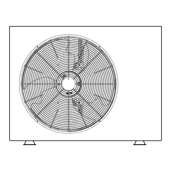
- Page 4 NOTE ● The pictures in this manual are for reference only, please refer to the actual product.
-
Page 5: Safety Precautions
1 SAFETY PRECAUTIONS The precautions listed here are divided into the following types.They are quite important, so be sure to follow them carefully. Meanings of DANGER, WARNING, CAUTION and NOTE symbols. INFORMATION ● Read these instructions carefully before installation. Keep this manual in a handy for future reference. ●... - Page 6 DANGER • Before touching electric terminal parts, turn off power switch. • When service panels are removed, live parts can be easily touched by accident. • Never leave the unit unattended during installation or servicing when the service panel is removed. •...
- Page 7 • Do not install the unit in the following places: - Where there is mist of mineral oil, oil spray or vapors. Plastic parts may deteriorate, and cause them to come loose or water to leak. - Where corrosive gases (such as sulphurous acid gas) are produced. Where corrosion of copper pipes or soldered parts may cause refrigerant to leak.
-
Page 8: General Introduction
2 GENERAL INTRODUCTION • These units are used for both heating and cooling the water of swimming pool, they can keep the pool water temperature stable at the set temperature to provide comfortable swimming condition in different seasons. • A wired controller is supplied with the unit. NOTE •... -
Page 9: Installation Site
4 INSTALLATION SITE WARNING • There is flammable refrigerant in the unit and it should be installed in a well-ventilated site. If the unit is installed inside, an additional refrigerant detection device and ventilation equipment must be added in accordance with the standard EN378. Be sure to adopt adequate measures to prevent the unit from being used as a shelter by small animals. -
Page 10: Location Selection In Cold Climates
Make sure there is enough space to install the unit. Set the outlet side at a right angle to the direction of the wind. Mount the unit on the foundation of concrete blocks to drain waste water from around the unit. If you install the unit on a frame, please install a waterproof plate on the underside of the unit to prevent water from coming in from the low side. -
Page 11: Installation Precautions
5 INSTALLATION PRECAUTIONS 5.1 Dimensions Model: 70/90/120/160/200 Unit: mm 2-G1.5" DN50 5.2 Shock absorption and fixations • Check the strength and levelness of the installation floor, ensure that the vibration and noise of the unit are minimized. • Bolts, nuts, gaskets, shock pads, foundations are not provided, please purchase or contact the installer. 5.2.1 Install with bolt shock pad Item Name... -
Page 12: Drain Hole Position
5.2.1 Install with perforated shock pad and bolts Item Name Specification Quantity External diameter 30 Perforated shock pad Inner diameter ≥ 10 Bolt Gasket Solid foundation W*H*L: 100*100*500 5.3 Drain Hole Position Drain hole Drain hole Drain connection 31mm Connect to drain hose •... -
Page 13: Inlet & Outlet Water Pipes
5.4 Inlet & Outlet Water Pipes Loose joint water outlet water inlet 5.5 Field Wiring Junction box For installation and connection of the wired controller, please refer to the Installation & owner’s manual of Wired controller. UNIT POWER SUPPLY 1-phase NOTE The ground fault circuit interrupter must be 1 high-speed type of 30mA(<0.1s). -
Page 14: Safety Device Requirement
When connecting to the power supply terminal, use the circular wiring terminal with the insulation casing (see Figure 1). Use power cord that conforms to the specifications and connect the power cord firmly. To prevent the cord from being pulled out by external force, make sure it is fixed securely. -
Page 15: Typical Applications
6 TYPICAL APPLICATIONS Water outlet Chlorinator cell Valve Water supply Water inlet Sand filter Pool (or other filter) Water pump Installation items: All the items except the heat pump in the illustration are not supplied, please purchase or contact the installer. NOTE Please follow these steps when using for the first time 1.Open valve and charge water. -
Page 16: Main Components
Item Description Item Description Compressor Electronic expansion valve Discharge temperature sensor Filter High pressure switch Filter Suction temperature sensor Titanium heat exchanger Low pressure switch Gas refrigerant temperature sensor 4-way valve Liquid refrigerant temperature sensor Fin-coil heat exchanger Water outlet temperature sensor Ambient temperature sensor Water inlet temperature sensor Coil temperature sensor... -
Page 17: Inverter Drive Board
4-way Valve Electronic expansion valve Flow switch 7.3 Inverter Drive Board CN13 CN10 Code Assembly unit Code Assembly unit Compressor connection port U Port for communication with main control board (CN10) Compressor connection port V Input port L for rectifier bridge(CN1) Compressor connection port W Input port N for rectifier bridge(CN2) Port for fan(CN32) -
Page 18: Main Control Board
7.4 Main Control Board COMM COMM CN16 on/off H-SEN H-SEN TWin TWout CN10 CN19 CN28 CN29 TRANS OUT AC 12V P E Q P E Q X Y E Code Assembly unit Code Assembly unit Power input port from Main control board (CN1) Port for communication with wire controller AB (CN29) Port for communication with Inverter module Port for transformer output(CN28) -
Page 19: Connection Of Optional Function
7.5 Connection Of Optional Function 1) For smart grid: The unit has smart grid function, there are two ports on PCB to 1) SG=ON, EVU=ON. connect SG signal and EVU signal as following: If the heat pump in heating mode: ●... -
Page 20: Start-Up And Configuration
8 START-UP AND CONFIGURATION The unit should be configured by the installer to match the installation environment (outdoor climate, installed options, etc.) and user expertise. CAUTION It is important that all information in this chapter is read sequentially by the installer and that the system is configured as applicable. -
Page 21: Final Checks And Test Run
9 FINAL CHECKS AND TEST RUN The installer is obliged to verify correct operation of unit after installation Final checks Before switching on the unit, read following recommendations: • When the installation and parameter setting are completed, cover all the sheet metal of the unit well. •... -
Page 22: Notes For Maintenance & Repair
10.2 Notes For Maintenance & Repair 10.2.1 Top panel remove Junction box M4 screw*2 Unscrew these 2 screws before remove the top panel 10.2.2 Titanium heat exchanger replace The titanium heat exchanger’s remove and installation can only by loosening the copper tube at the top (use welding torch). - Page 23 10.2.3 Inverter drive board replace Remove the connecting wires from the inverter drive board before taking it out if necessary...
-
Page 24: Troubleshooting
11 TROUBLESHOOTING Error code Display Malfunction or Protection Ambient temp. sensor (T4) out of operation range High temperature protection of inverter module Water flow malfunction(after 3 times E8) Communication malfunction between controller and main control board Total outlet water temp.sensor(T1) malfunction Air side heat exchanger temperature sensor (T3)malfunction The ambient temperature sensor (T4)malfunction Water flow malfunction... - Page 25 Common malfunctions/protections and solutions in heating mode Errorcode Malfunction / protection Solutions 1. Restart the unit. 2. Power off the unit,unplug and plug the cable of display, and then power on. Communication failure 3. If all the above checks are ok, the fault still exists, please contact the installer or retailer.
-
Page 26: Technical Specifications
12 TECHNICAL SPECIFICATIONS Model Power supply 220-240V~ 50Hz Boost Heating capacity* 10.30 12.80 14.50 18.70 21.80 Boost COP* 6.60 6.00 6.35 5.10 4.40 Heating capacity* 7.16 9.15 12.50 16.00 18.80 COP* 7.50 6.80 7.00 6.00 5.20 Boost Heating capacity** 7.30 9.30 10.50 15.00... -
Page 27: Information Servicing
13 INFORMATION SERVICING 1) Checks to the area Prior to beginning work on systems containing flammable refrigerants, safety checks are necessary to ensure that the risk of ignition is minmised. For repair to the refrigerating system, the following precautions shall be complied with prior to conducting work on the system. - Page 28 11) Repair to intrinsically safe components Do not apply any permanent inductive or capacitance loads to the circuit without ensuring that this will not exceed the permissible voltage and current permitted for the equipment in use. Intrinscially safe components are the only types that can be worked on while live in the presence of a flammable atmosphere.
- Page 29 17) Decommissioning Before carrying out this procedure, it is essential that the technician is completely familiar with the equipment and all its detail. It is recommended good practice that all refrigerants are recovered safely. Prior to the task being carried out, an oil and refrigerant sample shall be taken.
- Page 31 NOTE:...
Need help?
Do you have a question about the KSWP-70 DR8 and is the answer not in the manual?
Questions and answers