Table of Contents
Advertisement
Advertisement
Table of Contents

Subscribe to Our Youtube Channel
Related Manuals for Kaysun Aquantia KHPMS-BI Series


Summary of Contents for Kaysun Aquantia KHPMS-BI Series
- Page 1 INSTALLATION & OWNER’S MANUAL Aquantia Air/Water Heat Pumps KHPMS-BI Set - Outdoor Unit KHP-BI 4 DVR KHP-BI 8 DVR KHP-BI 10 DVR KHP-BI 6 DVR IMPORTANT NOTE: Thank you very much for purchasing our product, Before using your unit , please read this manual carefully and keep it for future reference.
-
Page 2: Table Of Contents
CONTENTS 1 SAFETY CONSIDERATIONS ................02 2 ACCESSORIES ......................05 • 2.1 Accessories supplied with the unit ................05 3 BEFORE INSTALLATION ..................05 4 IMPORTANT INFORMATION FOR THE REFRIGERANT...... 05 5 INSTALLATION SITE ....................07 • 5.1 Selecting a location in cold climates ................08 •... - Page 3 9 OVERVIEW OF THE UNIT ..................17 • 9.1 Disassembling the unit ....................17 • 9.2 Electronic control box ....................18 • 9.3 4~10kW units ......................19 10 TEST RUNNING ......................21 11 PRECAUTIONS ON REFRIGERANT LEAKAGE ........21 12 TURN OVER TO CUSTOMER ................
- Page 5 4/6 kW 8/10 kW Wiring diagram:8/10kW for example Electric Control System 4/6 kW 8/10 kW Refrigerant System Please remove the hollow plate after installation.
-
Page 6: Safety Considerations
1 SAFETY PRECAUTIONS The precautions listed here are divided into the following types. They are quite important, so be sure to follow them carefully. Meanings of DANGER, WARNING, CAUTION and NOTE symbols. INFORMATION • Read these instructions carefully before installation. Keep this manual in a handy for future reference. •... - Page 7 DANGER • Before touching electric terminal parts, turn off power switch. • When service panels are removed, live parts can be easily touched by accident. • Never leave the unit unattended during installation or servicing when the service panel is removed. •...
- Page 8 • Do not install the unit in the following places: - Where there is mist of mineral oil, oil spray or vapors. Plastic parts may deteriorate, and cause them to come loose or water to leak. - Where corrosive gases (such as sulphurous acid gas) are produced. Where corrosion of copper pipes or soldered parts may cause refrigerant to leak.
-
Page 9: Accessories
2 ACCESSORIES 2.1 Accessories supplied with the unit Installation Fittings Name Shape Quantity Outdoor unit installation & owners manual (this book) Technical data manual Water outlet connection pipe assembly Energy label 3 BEFORE INSTALLATION • Before installation Be sure to confirm the model name and the serial number of the unit. • Handling 1. -
Page 10: Important Information For The Refrigerant
2. While handling the unit keep both sides of the sling level. keep your back straight 3. After mounting the unit,remove the sling from the unit by pulling 1 side of the sling. CAUTION • To avoid injury, do not touch the air inlet and aluminum fins of the unit. • Do not use the grips in the fan grills to avoid damage. •... -
Page 11: Installation Site
CAUTION • Frequency of Refrigerant Leakage Checks - Equipment that contains less than 3 kg of fluorinated greenhouse gases or hermetically sealed equipment, which is labelled accordingly and contains less than 6 kg of fluorinated greenhouse gases shall not be subject to leak checks. - For unit that contains fluorinated greenhouse gases in quantities of 5 tonnes of CO2 equivalent or more,but of less than 50 tonnes of CO2 equivalent,at least every 12 months, or where a leakage detection system is installed, at least every 24 months. - This air-conditioning unit is a hermetically sealed equipment that contains fluorinated greenhouse gases. - Only certificated person is allowed to do installation, operation and maintenance. 5 INSTALLATION SITE WARNING • Be sure to adopt adequate measures to prevent the unit from being used as a shelter by small animals.Small animals making contact with electrical parts can cause malfunction, smoke or fire. Please instruct the customer to keep the area around the unit clean. -
Page 12: Selecting A Location In Cold Climates
5.1 Selecting a location in cold In normal condition,refer to the figures below for installation of the unit: climates Refer to "Handling" in section “4 Before installation” ( ) NOTE wall or obstacle When operating the unit in cold climates, be sure >300 to follow the instructions described below. Air inlet >300 Maintain... -
Page 13: Installation Precautions
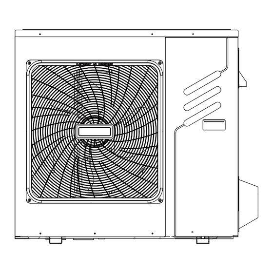
6 INSTALLATION PRECAUTIONS 6.1 Dimensions 8/10 kW (unit: mm) 4/6 kW (unit: mm) Fig: 6-1 Fig: 6-2 Model 4/6kW 8/10kW 1075 6.2 Installation requirements • Check the strength and level of the installation ground so that the unit may not cause any vibrations or noise during the operation. -
Page 14: Drain Hole Position
6.3 Drain hole position Drain hole Drain hole This drain hole is covered by rubber plug. If the small drain hole can not meet the drainage requirements, the big drain hole can be used at the same time. 8/10kW 4/6 kW Fig: 6-5 CAUTION It's necessary to install an electrical heating belt if water can't drain out in cold weather even the big drain hole has... -
Page 15: Installation The Connecting Pipe
<1/2 H Fig: 6-7 Unit A(mm) B1(mm) B2(mm) C(mm) 4~10kW ≥3000 ≥2000 ≥150 ≥600 2) In case of installing multiple units in lateral connection per row. <1/2 H ≥500mm ≥500mm Fig: 6-8 Unit A(mm) B1(mm) B2(mm) C(mm) 4~10kW ≥3000 ≥2000 ≥300 ≥600 7 INSTALL THE CONNECTING PIPE... -
Page 16: Leakage Detection
CAUTION • Please pay attention to avoid the components where it is connecting to the connecting pipes. • To prevent the refrigerant piping from oxidizing inside when welding, it is necessary to charge nitrogen, or oxide will chock the circulation system. •... -
Page 17: Connecting Method
7.4 Connecting method Outdoor Unit ≥300mm ≥300mm Figure 7-4 Indoor Unit max. difference in height Figure 7-5 CAUTION CAUTION The largest level difference between indoor unit and outdoor unit should not exceed 20m (if the outdoor unit is above) or 15m (if the outdoor unit is below). Additionally: (i) If the outdoor unit is above and the level difference is greater than 20m, it is recommended that an oil return bend with dimensions as specified in Figure 7-4 is set every 5m in the gas pipe of the main pipe;... -
Page 18: Remove Dirt Or Water In The Pipe
Models 4~10 kW Max.piping length Max difference in height when outdoor unit is upsite Max difference in height when outdoor unit is downside 7.5 Remove Dirt or Water in the Pipes 1) Make sure there is no any dirt or water before connecting the piping to the outdoor and indoor units. 2) Wash the pipes with high pressure nitrogen, never use refrigerant of outdoor unit. -
Page 19: Outdoor Unit Wiring
8 OUTDOOR UNIT WIRING WARNING A main switch or other means of disconnection, having a contact separation in all poles, must be incorporated in the fixed wiring in accordance with relevant local laws and regulations. Switch off the power supply before making any connections. Use only copper wires. Never squeeze bundled cables and make sure they do not come in contact with the piping and sharp edges. Make sure no external pressure is applied to the terminal connections. All field wiring and components must be installed by a licensed electrician and must comply with relevant local laws and regulations. -
Page 20: Remove The Switch Box Cover
8.3 Safety device requirement 1. Select the wire diameters( minimum value) individually for each unit based on the table 8-1 and table 8-2, where the rated current in table 9-1 means MCA in table 9-2. In case the MCA exceeds 63A, the wire diameters should be selected according to the national wiring regulation. -
Page 21: Overview Of The Unit
OUTDOOR UNIT INDOOR UNIT P Q E POWER SUPPLY NOTE The ground fault circuit interrupter must be a high-speed type breaker of 30 mA (<0.1 s). Please use 3-core shielded wire. 8.5 To finish the outdoor unit installation insulate and fix the refrigerant piping and interconnection cable as follows: Gas pipe Gas pipe insulation Finishing tipe Liquid pipe... -
Page 22: Electronic Control Box
4/6kW 8/10kW Door 1 To access to the compressor and Door 1 To access to the compressor and electrical parts. electrical parts WARNING • Switch off all power — i.e. unit power supply and backup heater and domestic hot water tank power supply (if applicable) —... -
Page 23: 10Kw Units
PCB A PCB B 8/10kW NOTE The picture is for reference only, please refer to the actual product. 9.3 4~10kW units 1) PCB A, Inverter module... - Page 24 Coding Assembly unit Coding Assembly unit Compressor connection port U Reserved(CN302) Compressor connection port V Port for communication with PCB B(CN32) Compressor connection port W Input port L for rectifier bridge(CN501) Output port for +12V/5V(CN20) Input port N for rectifier bridge(CN502) Port for fan(CN19) 2) PCB B, Main control board Coding Assembly unit Coding...
-
Page 25: Test Running
10 TEST RUNNING Operate according to "key points for test running" on the electric control box cover. CAUTION ● Test running can not start until the outdoor unit has been connected to the power for 12 hours. ● Test running can not start until all the valves are affirmed open. ● Never make the forced running .(Or the protector sits back, danger will occur.) 11 PRECAUTIONS ON REFRIGERANT LEAKAGE When the refrigerant charge in appliance is more than 1.842kg, following requirements should be complied with. ● Requirements for charge limits in unventilated areas: The maximum refrigerant charge in appliance shall be in accordance with the following: = 2.5 x (LFL) -
Page 26: Turn Over To Customer
Outdoor Unit Indoor Unit Room is filled of leakage refrigerant. (All refrigerant has leaked out.) 8/10kW Fig.11-2 Indoor unit A. Ventilation peristome B. Leak alarm related to mechanical ventilator (Leak hunting siren should be installed in places easily keep refrigerant) Fig.11-3 12 TURN OVER TO CUSTOMER The owner's manual of indoor unit and owner's manual of outdoor unit must be turned over to the customer. - Page 27 WARNING • Turn off any combustible heating devices, ventilate the • Ask your dealer for installation of the heat pump. room, and contact the dealer where you purchased the Incomplete installation performed by yourself may result in unit. a water leakage, electric shock, and fire. Do not use the heat pump until a service person confirms that the portion where the refrigerant leaks is repaired.
-
Page 28: Operation And Performance
NOTE • Never expose little children, plants or animals directly to the air flow. When the protection equipment starts, please shut down the Adverse influence to little children, animals and plants may manual power switch, and restart operation after problem is result. solved. • Do not allow a child to mount on the outdoor unit or avoid placing any object on it. -
Page 29: Error Codes
13.8 Error codes When a safety device is activated, an error code will be displayed on the user interface. A list of all errors and corrective actions can be found in the table below. Reset the safety by turning the unit OFF and back ON. In case this procedure for resetting the safety is not successful, contact your local dealer. - Page 30 ERROR MALFUNCTION FAILURE CAUSE CODE OR PROTECTION AND CORRECTIVE ACTION 1. Strong wind or typhoon below toward to the fan, to make the fan running in the opposite direction. Change the unit direction or make The DC fan failure shelter to avoid typhoon below to the fan. 2.fan motor is broken, change a new fan motor.
- Page 31 ERROR MALFUNCTION FAILURE CAUSE CODE OR PROTECTION AND CORRECTIVE ACTION Heating mode, DHW mode: 1. The water flow is low; water temp is high, whether there is air in the water system. Release the air. 2. Water pressure is lower than 0.1Mpa, charge the water to let the pressure in the range of 0.15~0.2Mpa. 3.
- Page 32 ERROR MALFUNCTION FAILURE CAUSE CODE OR PROTECTION AND CORRECTIVE ACTION 1. Heat exchanger cover is not removed. Remove it. 2. Heat exchanger is dirty or something is block on the surface. High temperature protection Clean the heat exchanger or remove the obstruction. of refrigerant outlet temp of condenser.
-
Page 33: Technical Specifications
14 TECHNICAL SPECIFICATIONS KHP-BI 4 DVR (4kW) KHP-BI 8 DVR (8kW) Model (Capacity mark) KHP-BI 6 DVR (6kW) KHP-BI 10 DVR (10kW) Power supply 220-240V~ 50Hz Rated power input 2.65kW 3.80kW Rated current 11.3A 16.7A Norminal capacity Refer to the technical data Dimensions (WxH*D)[mm] 974*857*378 1075*965*411... -
Page 34: Information Servicing
15 INFORMATION SERVICING 1) Checks to the area Prior to beginning work on systems containing flammable refrigerants, safety checks are necessary to ensure that the risk of ignition is minmised. For repair to the refrigerating system, the following precautions shall be complied with prior to conducting work on the system. 2) Work procedure Works shall be undertaken under a controlled procedure so as to minimise the risk of a flammable gas or vapour being present while the work is being performed. 3) General work area All mintenance staff and others working in the local area shall be instructed on the nature of work being carried out. - Page 35 b) Particular attention shall be paid to the following to ensure that by working on electrical components, the casing is not altered in such a way that the level of protection is affected. This shall include damage to cables, excessive number of connections, terminals not made to original specification, damage to seals, incorrect fitting of glands, etc.
- Page 36 • Cylinders shall be kept upright. • Ensure that the refrigeration system is earthed prior to charging the system with refrigerant. • Label the system when charging is complete(if not already). • Extreme care shall be taken not to overfill the refrigeration system. • Prior to recharging the system it shall be pressure tested with OFN. The system shall be leak tested on completion of charging but prior to commissioning.
- Page 37 ANNEX A: Refrigerant cycle Cooling Heating Item Description Item Description Compressor Outdoor temperature sensor 4-Way Valve Outdoor exchanger sensor Gas-liquid separator Stop valve (gas) Air side heat exchanger Stop valve (liquid) Electronic expansion Valve High Pressure Switch Single-way electromagnetic valve Low Pressure Switch Pipe joint Pressure valve...
- Page 38 ANNEX B: Electrically controlled wiring diagram 4~10kW CN19 CN20 W(C) BLUE V(S) BLACK PCB A,Inverter U(R) board for 1phase CN501 CN502 ACL ACN BROWN BLUE COMP CN31 CN17 XS3 XP3 L-PRO L-OUT N-OUT N-OUT CN28 CN27 CN37 H-PRO XS4 XP4 PCB B,Main control board WHITE for 1phase...
Need help?
Do you have a question about the Aquantia KHPMS-BI Series and is the answer not in the manual?
Questions and answers