Table of Contents

Related Manuals for Kaysun KHPA2 300S


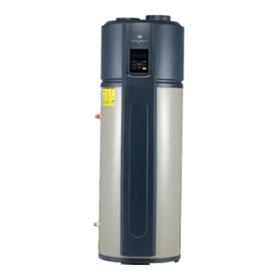
Summary of Contents for Kaysun KHPA2 300S
- Page 1 INSTALLATION, TECHNICAL & OWNER'S MANUAL Domestic Hot Water Heat Pumps COMPAK KHPA2 300S KHPA2 190S Thank you very much for purchasing our product. Before using your unit, please read this manual carefully and keep it for future reference.
-
Page 3: Table Of Contents
Safety considerations Introduction Before installation Handling Selecting the installation site Water connections Aeraulic connections Electrical connections Start-up Control Maintenance Residual risks / Decommissioning Technical data Elfocontrol Modbus Protocol Pay particular attention to: INSTALLER use USER use... -
Page 4: Safety Considerations
SAFETY CONSIDERATION S The precautions in this manual are divided as indicated on the side. Meaning of the symbols DANGER, They are important, so make sure you follow WARNING, CAUTION and NOTE them closely. DAN GER Please read these instructions carefully before ... - Page 5 SAFETY CONSIDERATION S Never use a flammable spray such as hair spray, lacquer paint near the unit, it may cause a fire. remove, cover deface permanent instructions, lables, or the data label from either the outside of the unit or inside of unit panels.
- Page 6 SAFETY CONSIDERATION S System will stop restart heating automatically. A continuous power supply for water heating is necessary, except service and maintenance. Keep this manual with the wiring diagram in an accessible place for the operator. Children should be supervised to ensure that ...
- Page 7 SAFETY CONSIDERATION S General instructions Preliminaries Read carefully the IOM and use the unit strictly according to the instructions in order to avoid personal injuries, damages to the unit, damages to property and litigations. Our company does not assume any legal liability for any damage caused by improper use of the unit.
- Page 8 SAFETY CONSIDERATION S Any use other than intended does not involve the manufacturer in any commitment or obligation. Hydraulic system Components Selection and installation of system components must be carry out by installer. Water quality The water quality is determined by the following factors, avoid therefore: Inorganic salts ...
- Page 9 SAFETY CONSIDERATION S Electric system The characteristics of the electrical lines must be determined by specialized personnel able to This unit is required reliable earthing before usage, otherwise might design electrical installations; moreover, the lines cause injury. must be in conformity with regulations in force. Operate in compliance with safety regulations in force .
- Page 10 SAFETY CONSIDERATION S Before starting work, verify that the sectioning device at the start of the unit power line is open, blocked and equipped with sign warning. First create the earthing connection. After wire connection, check it again and make sure the correctness before power on.
- Page 11 SAFETY CONSIDERATION S standby mode; maintenance; what to do / what not to do in case of breakdown. Data update Continual product improvements may imply manual data changes Visit manufacturer web site for updated data.
-
Page 12: Introduction
INTRODUCTION Safety Operate in compliance with safety regulations in force . Use single protection devices: gloves, glasses, helmet etc. NOTE Before beginning the work, ensure you that have the final project for installing the aeraulic, hydraulic, electric,drains and positioning the units. Unit identification Pay particular attention to: ⇒... - Page 13 INTRODUCTION Discharges unit connected Electric connections Repair parts When ordering repair parts please always give the following information: Model, serial and product number. Parts name. Picture All the picture in this manual are for explanation purpose only. They may be slightly different from the unit you purchased (depand on model).
- Page 14 INTRODUCTION Parts unit - 190S Code Description The codes are subject to being updated: contact the authorised service centre for the updated code...
- Page 15 INTRODUCTION Parts unit - 190S Code Description The codes are subject to being updated: contact the authorised service centre for the updated code...
- Page 16 INTRODUCTION Parts unit - 190S Code Description The codes are subject to being updated: contact the authorised service centre for the updated code...
- Page 17 INTRODUCTION Parts unit - 300S Code Description El ectr ical heate r The codes are subject to being updated: contact the authorised service centre for the updated code...
- Page 18 INTRODUCTION Parts unit - 300S Code Description The codes are subject to being updated: contact the authorised service centre for the updated code...
- Page 19 INTRODUCTION Parts unit - 300S Code Description The codes are subject to being updated: contact the authorised service centre for the updated code...
-
Page 20: Before Installation
BEFO RE INSTALLATION Reception Before accepting the delivery you have to check: that the unit hasn’t been damaged during transport. check that the materials delivered correspond with that indicated on the transport document comparing the data with the identification label positioned on the packaging. In case of damage or anomaly: Write down on the transport document the damage you found ... -
Page 21: Handling
HANDLIN G Handling Check that all handling equipment complies with local safety regulations (cran, forklifts, ropes, hooks, etc.). Provide personnel with personal protective equipment suitable for the situation, such as helmet, gloves, accident-prevention shoes, etc. Observe all safety procedures in order to guarantee the safety of the personnel present and the of material. - Page 22 HANDLIN G Packaging removing Be careful not to damage the unit. Keep packing material out of children’s reach it may be dangerous. Recycle and dispose of the packaging material in conformity with local regulations. Cut the hoops Cut along the joint (A) Rear Front Handle for handling...
-
Page 23: Selecting The Installation Site
SELECTIN G THE INSTAL LATION SITE The installation has been implemented by qualified technical personnel only and that the instructions contained in the present manual and the local regulations in force have been adhered to. Choose the installation place according to the following criteria: ... - Page 24 SELECTIN G THE INSTAL LATION SITE NOTE Installing the unit in any of the following places may lead to malfunction: The site contains mineral oils such as cutting lubricant Seaside where the air contains much salt. Hot spring area where corrosive gases exist, e.g., sulfide gas. ...
- Page 25 SELECTIN G THE INSTAL LATION SITE NOTE Install the unit in the indoor space, it is not allow to install the unit at the rainy space In case of rain entering to internal components of the unit, the component might be damaged or causing physical danger. Check that the floor can support the weight of the unit in operation (dimensional see) Unit in bubble level...
-
Page 26: Water Connections
WATER CONNECTIONS Water feature N ote Fill the storage tank (DHW) only during the unit start-up. If the house is not immediately lived,or the unit is turned long periods, empty the storage tank to avoid the stagnation of the water, or with temperatures close to 0°C the risk of freeze. - Page 27 Dielectric joints (Provided by the customer) In order to prevent the formation of galvanic couples between iron/ copper (risk of corrosion), do not connect the domestic hot water connection directly to the copper pipes. Install a dielectric joint on the domestic hot water inlet and outlet pipes N ote The above devices must be installed downstream of the...
- Page 28 WATER CONNECTIONS Hydraulic connections Unit with solar DHW outlet Aqueduct inlet DWH recirculation Solar outlet Solar inlet Electrical connections → page 76 Connecting drains (Unit Solar) Upper condensate outlet ø 10 Condensate drain ø 10 Domestic hot water safety valve Storage tank discharge Drain accumulation / drain pit...
- Page 29 WATER CONNECTIONS Condensate drain The condensate must be disposed in order to avoid damages to Block the condensate drain pipe with people and things. the clip supplied. To smoothly drain condensate, the unit should be installed at a horizontal floor. Otherwise, the drain vent is ensured at the lowest place.
- Page 30 WATER CONNECTIONS Water system N ote In case of installing the unit at a place where outside temperature below freezing point, insulation must be provided for all hydraulic components. Indicative plumbing diagram The system components must be defined by Designer and Installer (ex. expansion tanks, vents, taps, calibration/safety valves etc.) Pressure reducing valve Water treatment devices (water softener, etc.)
- Page 31 WATER CONNECTIONS Unit with solar Indicative plumbing diagram The system components must be defined by Designer and Installer (ex. expansion tanks, vents, taps, calibration/safety valves etc.) Pressure reducing valve Water treatment devices (water softener, etc.) Filter Y Non-return valve Safety valve with discharge DHW expansion vessel Storage drain Hot water circulator (recirculation) with check...
-
Page 32: Aeraulic Connections
AERAULIC CONN ECTIONS Possible installations The unit must be installed inside the building, preferably in a technical room or a laundry room or a garage. At any rate, it is always preferable to avoid installing the unit near bedrooms or in rooms that must be protected from noise. - Page 33 AERAULIC CONN ECTIONS Unit attacks 190S Aeraulic design criteria The dimensioning and the correct execution of the aeraulic connections are critical to ensure the unit operating and an appropriate level of quietness in the served area. Pressure loss in the duct will reduce the air flow, which can cause a reduction in efficiency of the unit.
- Page 34 AERAULIC CONN ECTIONS Avoid recirculation of exhaust/return air Use elbows with a 90° downward bend (1,2) 800mm (3,4) Minimum distance External air return positioned in an area with a low concentration of impurities (dust, odours, exhaust fumes, etc.). ...
- Page 35 AERAULIC CONN ECTIONS In terms of the unit connect with duct reaching to outdoor, a reliable water-resistant measure must be conduct on the duct, to prevent water from dropping into internal of the unit . In case the water entering to internal components of the unit, the component might be damaged or causing physical danger.
- Page 36 AERAULIC CONN ECTIONS Grid to prevent small animals or leaves from entering inside (provided by the customer) Installing at the unit inlet. In terms of the unit with duct, grid there must be put on the position of duct inlet. (Provided by the customer) The grid must be provided on the intake outlet of the external air or on the duct easily accessible for routine maintenance (Provided by the customer), the mesh size is about 1.
-
Page 37: Electrical Connections
ELECTRICAL CONNECTIO NS Electrical wiringdiagram - Unit 190S A - Wire comes out from tank,must connect with the corresponding component. POWER SUPPLY Wiring diagram of tank inside The L,N wires,which get through the zero-phase electricity mutual inductor, must keeping the sam direction during wring, otherwise, system malfunction may caused. - Page 38 ELECTRICAL CONNECTIO NS Electrical wiringdiagram - Unit 300S A - Wire comes out from tank,must connect with the corresponding component. POWER SUPPLY Wiring diagram of tank inside The L,N wires,which get through the zero-phase electricity mutual inductor, must keeping the sam direction during wring, otherwise, system malfunc- tion may caused.
- Page 39 ELECTRICAL CONNECTIO NS All electrical operations should be performed by trained personnel ha- ving the necessary requirements by the regulations in force and being informed about the risks relevant to these activities. This unit is required reliable earthing before usage, otherwise might MIin.
- Page 40 ELECTRICAL CONNECTIO NS Electric Connection The power supply should be an independent circuit with rated voltage. Power supply circuit should be earthed effectively. Do not use water pipes to earthing connection of the unit The wiring must be performed by professional technicians in accordance with national wiring regulations and this circuit diagram.
-
Page 41: Start-Up
START-UP N ote If the unit has been tipped during transport, wait at least 2 hours before starting it up General The indicated operations should be done by qualified technician with specific training on the product. Upon request, the service centres performing the start-up. The electrical, water connections and the other system works are by the installer. - Page 42 START-UP Yes / No Preliminary checks The flooring must be able to support the weight of the unit when full with water (see dimensional) Unit installed inside, in a vertical position and sheltered from freezing temperatures. The site location must be free from any corrosive elements in the atmosphere such as sulfur, fluorine, and chlorine and dust in excessive quantities.
- Page 43 START-UP Yes / No Post Installation Review Understand how to use the User Interface Module to set the various modes and functions. Periodically check of the condensate drain pan and lines. IMPORTANT: Water coming from the plastic shroud is an indicator that both condensation drain lines may be blocked.
- Page 44 START-UP Verify tensions - Absorbitions Check that the air and water temperatures are within the operating limits. With unit at steady state, i.e. in stable and close-to-work conditions, check: supply voltage unit total absorption absorption of each electric load.. ...
- Page 45 START-UP About Running 1 System Structure Figure Water outlet Unit has two kinds of heat sources: Heat pump(compressor) and electric heater. Temperature probe Unit will automatically select heat sources to heat water to the Storage tank (T5U) target temperature. 2 Water Temperature Display Electric heater The temperature shown on the display depends on the upper sensor.
- Page 46 START-UP After that it needs to be reset manually by pressing the red button on the TCO. N ote While the external temperature below than -7°C, heat pump efficiency will decrease dramatically, the unit will automatically shift to E-heater mode. Basic function How is the unit running If unit is OFF, press...
-
Page 47: Control
10 CONTROL Keyboard Display Operation Icons Description Icon On: screen locked. It can display: the normal water temperature; ① the remaining days in vacation mode; the temperature set when setting the parameters; the unit’s setting/operation parameters; On: WiFi connected;... - Page 48 10 CONTROL 6 programs can be set Corresponding icon on: program set. Corresponding icon off: program not set. ④ When the program is set, the corresponding icon flashes at a frequency of 2Hz and the set program will light up. Reserved ⑤...
- Page 49 10 CONTROL Each button press is only effective when the display is unlocked. Icon Description Use the button to change mode Default HYBRID mode Switches to E-heat mode ① Switches to VACATION mode Sets the vacation days (1-360 days) Switches to HYBRID mode + / UP Increases the corresponding value.
- Page 50 10 CONTROL DISINFECT Manually turns the disinfection function on icon flashes, then the unit heats the water to at least 70°C for disinfection. When the unit is being disinfected, press this button to can- cel the operation. icon turns off. ③...
- Page 51 10 CONTROL Timer button Enter the 6-segment programming setting; the ON icon is always on. Enter the TIMER ON setting; the hour value will flash Set the hour value Confirm the hour value and enter the minutes value Set the minutes value Confirm the minutes value and enter the TIMER OFF setting.
- Page 52 10 CONTROL CONFIRM / UNLOCK If the screen and buttons are unlocked, press this button to load the setting parameters after setting a parameter: ⑦ If it is pressed within 10 sec, the setting parameters will be loaded into the unit; ...
- Page 53 10 CONTROL Query function For the convenience of maintenance and debug, query function is available by press buttons together , then system running parameters will be shown one by one with following sequence by each pushing of Minutes bit Minutes bit Hour bit high Temp.
- Page 54 10 CONTROL Using the unit with the Comfort Home App Before starting, make sure: 1. Your smartphone is connected to your home WiFi network and you know the network password. 2. You are close to the appliances. 3. The 5GHz or 2.4GHz (preferable) wireless signal is enabled on your wireless router.
- Page 55 10 CONTROL Auto-restart If electricity power failed, unit can memorize all setting parameters, unit will be back to the previous setting when power recover. Button Auto Lock When there is no operation of button for 1 minute, button will be locked except Unlock button ( Press for 3 sec., unlock buttons..
- Page 56 10 CONTROL Problem solving Error Possible reason Solution Bad connection between power supply plug and socket; Connect again the supply plug Cold water tapped out and Setting water temperature too low; display screen Setting water temp. higher; Temper sensor broken ; extinguished Contact service center.
- Page 57 10 CONTROL Alarms Code Description Solution Maybe the connection between sensor and PCB has released or sensor has been broken. Error of sensor T5U (upper water temperature sensor) Contact a qualified person to service the unit. Maybe the connection between sensor and PCB has released or sensor has been broken.
- Page 58 10 CONTROL Alarms Code Description Solution System high pressure protection: Maybe because of system blocked, air or water or more Unit 300S : >=3.0Mpa active; <=2.4MPa inactive. refrigerant in system (after repair), water temperature sensor malfunction, ect. Unit 190S : P1 error code never appear because Contact a qualified person to service the unit.
- Page 59 10 CONTROL Frequent questions Q: Why compressor can't start immediately after setting? A: Unit will wait for 3 min to balance the pressure of system before start compressor again, it's a self protection logic of unit. Q: Why sometimes the temperature shown on the display panel decreased while unit is running? A: R.
-
Page 60: Maintenance
11 MAINTENAN CE Saftey Operate in compliance with safety regulations in force . Use single protection devices: gloves, glasses, helmet etc. General Maintenance must be performed by authorized centres or by qualified personnel The maintenance allows to: maintaining the unit efficient ... - Page 61 11 MAINTENAN CE Checklist for recommended regular checks Danger Disconnect the power supply before each operation intervention frequency (months) Air filter (inlet/outlet) Inner storage tank Electric heater Saftey valve Water filter Expansion vessel Checking for leaks* *Refer to the local provisions for implementation; in an extremely brief and purely indicative manner, the regulation specifies the following.
- Page 62 11 MAINTENAN CE Power supply Unit 190S Unit 300S Check the connection between power supply plug and socket and ground wiring regularly; Electronic anode The unit is equiped with a dynamic system for the tank active protection from corrosion. The anode is in active titanium. Periodical substitutions are not foreseen or maintenance.
- Page 63 11 MAINTENAN CE Storage tank It is recommended to clean the inner storage storage tank and e - heater to keep an efficient performance. Storage tank emptying If the unit needs cleaning, moving etc, the storage tank should be emptied. Witch off the unit: 1 close the cool water inlet valve (1);...
- Page 64 11 MAINTENAN CE Coil Accidental contact with the exchanger flaps can cause injuries from cut: use protective gloves. The coil must allow maximum thermal exchange, therefore, the surface must be clear from dirt and scaling. Clean the air inlet side. Use a soft brush or aspirator.
-
Page 65: Residual Risks / Decommissioning
12 RESIDUAL RISKS / DIS POSAL General In this section the most common situations are signalled. As the- se cannot be controlled by the manufacturer these could be a source of risk situations for people or things. Danger zone This is an area in which only an authorised operator may work. The danger zone is the area inside the unit which is accessible only with the deliberate removal of protections or parts thereof. - Page 66 12 RESIDUAL RISKS / DIS POSAL the panels are correctly closed and fixed. If there is a fire the temperature of the refrigerant could reach values that increase the pressure to beyond the safety valve with the consequent pos- sible projection of the refrigerant itself or explosion of the circuit parts that remain isolated by the closure of the tap.
- Page 67 12 RESIDUAL RISKS / DIS POSAL Hydraulic parts Defects in ducting , the attachments or the cut-off parts may cause a leak or water projection with the consequent damages to people, things or shortcircuit the unit. Disconnection Only authorised personnel must disconnect the unit. Avoid leak or spills into the environment.
- Page 68 12 RESIDUAL RISKS / DIS POSAL mechanical and electrical parts to be separated and disposed of as authorised. When machine components to be replaced for maintenance pur- poses are removed or when the entire unit reaches the end of its life and needs to be removed from the installation, waste should be separated by its nature and disposed of by authorised per- sonnel at existing collection centres.
-
Page 69: Technical Data
13 TECHNICAL DATA Dimensional 190S Compressor compartment Functional spaces Solar outlet 3/4” F Electric panel Anode Domestic hot water recirculation Unit keypad Water inlet 3/4” F Probe sump for solar Electric line input Water outlet 3/4”F Air inlet Condensate drain Solar inlet 3/4”F Air supply Size... - Page 70 13 TECHNICAL DATA Dimensional 300S Compressor compartment Functional spaces Solar outlet 3/4” F Electric panel Anode Domestic hot water recirculation Unit keypad Water inlet 3/4” F Probe sump for solar Electric line input Water outlet 3/4”F Air inlet Condensate drain Solar inlet 3/4”F Air supply Size...
- Page 71 13 TECHNICAL DATA General Technical Size 190S 300S Power and Efficiency Thermal power 1,62 2,30 Tout 15/12°C ( DB/WB), Tw,in 15 °C Total power absorbed 0,42 0,53 Tw,out 45°C 3,86 4,34 2,31 3,25 Thermal power Tout 43/26°C ( DB/WB), Tw,out 70°C --> 190S 0,546 0,627 Total power absorbed...
- Page 72 13 TECHNICAL DATA Size 190S 300S Ventilation Type of fan Centrifugal Air flow Available pressure head Integration Solar coil surface 1,10 1,30 Solar coil material Enamel Steel Maximum operating pressure 1. Inlet water temperature 15 °C, accumulator set 45°C, air on source side 15°C D.B /12°C W.B. 2.
- Page 73 Product fiche: water heaters / Scheda prodotto: scaldacqua Frigicoll S.A. Supplier's name / Nome del fornitore Series / Serie KHPA2 Model / Modello KHPA2 190S Size / Grandezza 190S Declared load profile / Profilo di carico dichiarato Class / Classe ηwh Thermostat temperature settings / Impostazioni di temperatura del...
- Page 74 Product fiche: water heaters / Scheda prodotto: scaldacqua Frigicoll S.A. Supplier's name / Nome del fornitore Series / Serie KHPA2 Model / Modello KHPA2 300S Size / Grandezza 300S Declared load profile / Profilo di carico dichiarato Class / Classe ηwh...
- Page 75 CATEGORIE BOMBA DE CALOR – producciόn de agua calientesanitaria CATEGORIA KHPA2 190S KHPA2 300S OMPLIES WITH THE FOLLOWING DIRECTIVES, INCLUDING THE MOST RECENT AMENDMENTS, AND THE RELEVANT NATIONAL HARMONISATION LEGISLATION CURRENTLY IN FORCE: ISULTA IN CONFORMITÀ CON QUANTO PREVISTO DALLE SEGUENTI DIRETTIVE...
- Page 76 SOLAR SYSTEM (PROVIDED B Y THE CUSTOMER) Installation by a qualified technician in possession of the technical-professional requisites according to the current national and local regulations in force in the territory. Scheme 1: the heat pump can also operate when the solar pump is in operation Electrical connections CN32 Solar controller signal input...
- Page 77 SOLAR SYSTEM (PROVIDED B Y THE CUSTOMER) Scheme 2: the heat pump cannot operate together with the solar pump. Electrical connections CN32 Solar controller signal input 220-240 Solar pump control 220-240 CN29 Unit control Enabled / disabled Operating logic CN32 (in) CN6 (out) SOLAR CN29...
-
Page 78: Elfocontrol 3 Evo
14 ELFOCONTROL3 EVO Option Equipped with: 12Vdc AL12X power supply unit Ethernet/485 converter Cat. 5 UTP Ethernet cable (5m long) For details, see instructions ELFOControl EVO manual TERMINATION JUMPER UNIT Ethernet/485 converter Modbus connection Baud rate = 9600 Termination Lenght = 8 Parity = none Stop bit = 1 Addressing... -
Page 79: Modbus Protocol
15 MODBUS PROTOCOL Unit set read command Register Data content Remarks address BIT15 Reserved BIT14 Reserved BIT13 Reserved BIT12 Reserved BIT11 Reserved BIT10 Reserved BIT9 Reserved BIT8 Reserved Power on/off BIT7 Reserved BIT6 Reserved BIT5 Reserved BIT4 Reserved BIT3 Reserved BIT2 Reserved BIT1... - Page 80 15 MODBUS PROTOCOL Register Data content Remarks address Operating mode 1:(invalid) 2:hybird, 3: e-heater, 4:vacation Water temperature in upper position of water tank, unit: °C. Send value = actual value*2+30 T5U temperature °C unit: °F. Send value = actual value Water temperature in lower position of water tank, unit: °C.
- Page 81 15 MODBUS PROTOCOL Register Data content Remarks address 1~19 E0~E9,EA,Eb,EC,Ed,EE,EF,EH,EL,EP 20~38 P0~P9,PA,Pb,PC,Pd,PE,PF,PH,PL,PP 39~57 H0~H9,HA,Hb,HC,Hd,HE,HF,HH,HL,HP Error Protect Code 58~76 C0~C9,CA,Cb,CC,Cd,CE,CF,CH,CL,CP 77~95 L0~L9,LA,Lb,LC,Ld,LE,LF,LH,LL,LP 96~114 b0~b9,bA,bb,bC,bd,bE,bF,bH,bL,bP unit: °C./ °F Maximum of Ts Send value = actual value unit: °C. / °F Minimum of Ts Send value = actual value unit: °C.
- Page 82 15 MODBUS PROTOCOL Unit operation status inquiry Register Data content Remarks address Operating mode 1:(reserved) 2:hybird 3: e-heater 4:vacation Water temperature in upper position of water tank, unit: °C. Send value = actual value*2+30 T5U temperature °C unit: °F. Send value = actual value Water temperature in lower position of water tank, unit: °C.
- Page 83 15 MODBUS PROTOCOL Register Data content Remarks address 1~19 E0~E9,EA,Eb,EC,Ed,EE,EF,EH,EL,EP 20~38 P0~P9,PA,Pb,PC,Pd,PE,PF,PH,PL,PP 39~57 H0~H9,HA,Hb,HC,Hd,HE,HF,HH,HL,HP Error Protect Code 58~76 C0~C9,CA,Cb,CC,Cd,CE,CF,CH,CL,CP 77~95 L0~L9,LA,Lb,LC,Ld,LE,LF,LH,LL,LP 96~114 b0~b9,bA,bb,bC,bd,bE,bF,bH,bL,bP unit: °C./ °F Maximum of Ts Send value = actual value unit: °C. / °F Minimum of Ts Send value = actual value unit: °C.
Need help?
Do you have a question about the KHPA2 300S and is the answer not in the manual?
Questions and answers