Table of Contents
Advertisement
Quick Links
Worcester V-Flow 51 / 52 Series
Class 150 / 300 reduced bore ball valves
WCENIM0026-01
Original Instructions
Copyright
All rights reserved. No part of these instructions may be reproduced, stored in a
retrieval system or transmitted in any form or by any means without prior permission
of Flowserve Flow Control.
Document Version
Initial Release, 01-APR-2018
These instructions must be read prior to installing, operating, and
maintaining this equipment.
Installation
Operation
Maintenance
Advertisement
Table of Contents

Related Manuals for Flowserve Worcester V-Flow 51 Series


Summary of Contents for Flowserve Worcester V-Flow 51 Series
- Page 1 Copyright All rights reserved. No part of these instructions may be reproduced, stored in a retrieval system or transmitted in any form or by any means without prior permission of Flowserve Flow Control. Document Version Initial Release, 01-APR-2018 These instructions must be read prior to installing, operating, and...
-
Page 2: Table Of Contents
Worcester V-Flow 51 / 52 Series User Instruction – WCENIM0026-01 CONTENTS General Information ........................ 2 Scope of manual ............................2 Disclaimer ..............................2 Health and Safety ........................3 Product Information ......................... 4 Certification ..............................4 Design ................................5 Storage ............................. 5 Installation .......................... -
Page 3: General Information
Genuine parts and accessories have been designed, tested, and incorporated into the products to help ensure continued product quality and performance in use. As Flowserve cannot test parts and accessories sourced from other vendors the incorrect incorporation of such parts and accessories may adversely affect the performance and safety features of the product. -
Page 4: Health And Safety
The valve must be installed in a system design to prevent excessive forces on the flanges and connectors. Consult Flowserve Flow Control technical sales before equipment is installed in areas subject to seismic activity or extreme climates. m) The valve should be protected by other devices to prevent over-pressurisation, e.g. -
Page 5: Product Information
Worcester V-Flow 51 / 52 Series User Instruction – WCENIM0026-01 Product Information Certification This product is compliant with the following EU regulations: a) Pressure Equipment Directive (PED) 2014/68/EU: If the ID plate carries the CE mark, PED number ‘2014/68/EU’, and the notified body identity number ‘0086’, the product complies with the PED. -
Page 6: Design
1.0 is allowable for all products. Those intended for ‘lethal service’ must have had non-destructive examination carried out in accordance with Appendix 7 of ASME BPVC Section VIII Division 1. Refer to Flowserve Flow Control technical sales for more information. -
Page 7: Installation
Worcester V-Flow 51 / 52 Series User Instruction – WCENIM0026-01 Installation Preparation a) The working area should be clean and clear of any debris that would contaminate the valve. b) When despatched, V-flow control valves contain special lubricants which aids the bedding in of the valve. -
Page 8: Operation
When operating the valve, avoid excessive loads on the wrench. Remote operation a) Where automation of valves is required, Flowserve Flow Control can supply pneumatic and electric actuators to cover a wide range of operating torques. b) Operation will be in accordance with installation, operation, and maintenance instructions for the relevant actuator. -
Page 9: Maintenance
Parts from different sized/rated valves must not be interchanged. c) Only Worcester authorised spare parts should be used. This includes basic components such as fasteners. Flowserve Flow Control accepts no responsibility if the valve is altered in any way without consent. -
Page 10: Refurbishment
Worcester V-Flow 51 / 52 Series User Instruction – WCENIM0026-01 Refurbishment Refer to the health and safety (see section 2) before starting any refurbishment work. Never remove or perform maintenance on a valve or flange joint unless the line has been fully depressurised, drained and where necessary, purged of toxic, explosive, or flammable media. -
Page 11: Reassembly
Worcester V-Flow 51 / 52 Series User Instruction – WCENIM0026-01 k) All sealing faces on the body, connector and ball must be checked for corrosion, erosion and scratches. If damage is found or there is any reason to believe that a part is damaged, replace the part. Valve parts should be cleaned using a suitable degreasing agent. - Page 12 Worcester V-Flow 51 / 52 Series User Instruction – WCENIM0026-01 Fit the original or spare metal seat ring complete with compressed PTFE/graphite seal in the other end. Replace the insert, and with the ball in the open position fully tighten to the correct torque (see section 11). k) Remove the insert and the spare seat ring.
-
Page 13: Technical Data
Worcester V-Flow 51 / 52 Series User Instruction – WCENIM0026-01 10 Technical Data 10.1 Gland nut torque The torque to be applied to the gland nut to ensure the correct amount of stem sealing. 10.2 Stem assembly torque The torque required to operate the assembled stem before the ball and seats are fitted to the valve. -
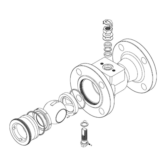
Page 14: Valve Exploded View Diagram
Worcester V-Flow 51 / 52 Series User Instruction – WCENIM0026-01 11 Valve Exploded View Diagram 11.1 DN15 – DN50 Valves Page 13 of 15... -
Page 15: Dn80 - Dn200 Valves
Worcester V-Flow 51 / 52 Series User Instruction – WCENIM0026-01 11.2 DN80 – DN200 Valves Page 14 of 15... - Page 16 When properly selected, this Flowserve product is designed to perform its intended function safely during its useful life. However, the purchaser or user of Flowserve products should be aware that Flowserve product might be used in numerous application under a wide variety of industrial service conditions.
Need help?
Do you have a question about the Worcester V-Flow 51 Series and is the answer not in the manual?
Questions and answers