
Subscribe to Our Youtube Channel
Related Manuals for Cleveland Controls 6650

Summary of Contents for Cleveland Controls 6650
- Page 1 CLEVELAND CONTROLS MODEL 6650 DIGITAL MANOMETER INSTRUCTION MANUAL DM-6650.02 Instruction Manual DM-6650.02...
-
Page 2: Table Of Contents
2.4 Nickel-cadmium Battery Pack ............8 2.5 Field Maintenance ............... 9 FIGURES Figure 1: Model 6650 Digital Manometer ......... 10 Figure 2: Integrated Pressure Sensing System ....... 10 Figure 3: Continuity Testing & Calibration of a Sensing Switch..12... -
Page 3: Introduction
The manometer is powered by a internal rechargeable battery pack. It can also be connected to an AC line via the power receptacle located on the rear panel and the provided AC cord. The Model 6650 Digital Manometer is factory calibrated and requires no routine maintenance. 1.2 SPECIFICATIONS Range: 0–10.00"... -
Page 4: Unpacking
Case: Black, high-impact plastic with tilt handle. 1.3 UNPACKING The shipping carton contains the following items: • Model 6650 Digital Manometer • AC cord set (P/N 27560) • Transparent flexible vinyl tubing, ¼" ID, ⅜" OD, 10' length (P/N 25781) •... -
Page 5: Operator Controls
They accept ⅛" miniature banana plugs, tip jacks, or wire leads to provide output for a remote recording or monitoring device (not included). • AC Power Receptacle is located on the rear panel and accepts the AC cord included with the Digital Manometer. Instruction Manual DM-6650.02... -
Page 6: Initial Checkout
1.6. 6 Touch the Normally Open (NO) wire to the Common (C) wire, and confirm that the NO LED (red) lights up. 1.6.7 Touch the Normally Closed (NC) wire to the Common (C) wire, and confirm that the NC LED (green) lights up. Instruction Manual DM-6650.02... -
Page 7: Operation
LED (NC) will be on, indicating that this circuit is closed. The red LED (NO) will remain off. 2.1.8 At the switch’s set point, as indicated on the manometer, the green NC LED will go out and the red NO LED will come on. Instruction Manual DM-6650.02... -
Page 8: Pressure Measurement
2.2 PRESSURE MEASUREMENT 2.2.1 The measuring element in the Model 6650 Digital Manometer is a piezoresistive pressure transducer. The transducer has a full scale input range of 0-10” wc and a linear output of 1-6 VDC.The Digital Manometer can be used to measure gauge or differential pressures or vacuums. -
Page 9: Field Maintenance
2.4.4 When the battery voltage drops below 10V, the “LO BAT” symbol lights up on in the display. 2.5 FIELD MAINTENANCE 2.5.1 The Model 6650 Digital Manometer is a solid state device with no moving parts and no scheduled maintenance requirements other than the battery charging procedure described in Section 2.4. -
Page 10: Figure 1: Model 6650 Digital Manometer
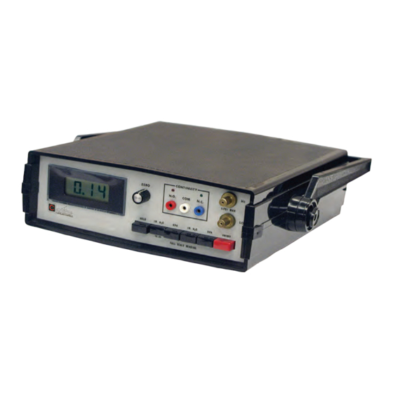
Figure 1: Model 6650 Digital Manometer A. Digital Readout: 3-½ digit liquid crystal display. B. Field calibration to null readout. C. Continuity tester to verify circuit integrity. D. Air sample ports accept ¼" ID flexible tubing. E. Operation selector allows various conversion factor readings. HOLD freezes the readout for value comparison. - Page 11 Also, keep them as short as possible.The tubing connecting the probe(s) to the tee(s)can be a different length. The manometer ships with a 10’ piece of tubing to be cut as needed. Instruction Manual DM-6650.02...
-
Page 12: Figure 3: Continuity Testing & Calibration Of A Sensing Switch
Figure 3: Typical application of Series 6650 Digital Manometer for continuity testing and calibration of an air pressure sensing switch. Cleveland Controls Tel: 216-398-0330 DIVISION OF UNICONTROL INC. Fax: 216-398-8558 1111 Brookpark Rd Email:saleshvac@unicontrolinc.com Cleveland OH 44109 Web page: http://www.clevelandcontrols.com...
Need help?
Do you have a question about the 6650 and is the answer not in the manual?
Questions and answers