Table of Contents
Advertisement
MCT-425, MCT-425C
Supervised Wireless PowerCode Smoke Detector
1. DESCRIPTION AND APPLICATIONS
The MCT-425 and MCT-425C are smoke-automatic fire detectors
with integral audible signal for open area protection, designed to
sense smoke (not gas, heat or flame) and fitted with a PowerCode
type UHF transmitter. MCT-425C is for CANADA only.
The smoke detector provides early warning of developing fire by
sounding an alarm with its built-in alarm horn, and by transmitting a
coded alarm signal to a PowerCode receiver or to a compatible
wireless alarm control panel. For UL approved installation use only
PowerMax+ control panel.
It must be borne in mind, though that effective prewarning of fire
accidents is only possible if the detector is located, installed and
maintained as described here.
2. SPECIFICATIONS
SMOKE DETECTOR
Alarm Sound Level: 85 dB at 3 m (10 feet)
TRANSMITTER AND CODING
Operating Frequency (MHz): 315, 433.92, 868.95, 869.2625 or
other frequency according to local requirements.
Transmitter's ID Code: 24-bit digital word, over 16 million
combinations, pulse width modulation.
Overall Message Length: 36 bits
Supervision: Automatic signaling at 60-minute intervals (315
MHz version), 15-minute interval (433.92, 868.95, 869.2625 MHz
versions) or according to the local standards.
Tamper Alerts: Tamper event (removal of the unit from its bracket)
is reported once. Tamper restore is reported when the tamper
switch is restored.
Transmission Indicator: Yellow LED lights upon transmission
(visible only when Switch SW-1 is ON).
ALARM REPORT:
Every 20 sec. for the first 3 minutes.
Every 3 min. for the next 27 minutes.
Alarm stops reporting after 30 min., or if the detector goes into
"alarm restore".
ELECTRICAL DATA
Power Source: 9 Volt alkaline or lithium.
Operation Voltage: From 7.2 V to 9 V.
Current Drain: 28 µA standby, 20 mA in operation
Smoke Density:
Europe: 0.15 – 0.2 dB/m
USA & CANADA: 0.61%/ft to 1.27%/ft
3. INSTALLATION
3.1 Disassembly
Separate the unit from its mounting bracket as shown in Figure 2.
BRACKET
1
Hold the
bracket with
one hand
Figure 2. Separating the Detector from Its Bracket
D-301296
DETECTOR
2
Rotate the
detector as
shown and
pull it from
the bracket
Installation Instructions
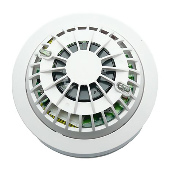
TEST BUTTON
&
RED LED
Figure 1. General View
Cover Range: 50 cubic meters (1765.5 cubic ft.)
Battery Life Expectancy:
Alkaline: at least 1 year (for typical use) for battery types
Eveready (Energizer) #E522, Duracell #MN1604, GP GP1604AU
Lithium: at least 1 year (for typical use) for battery type
Ultralife # U9VL-V.
Battery Supervision: Automatic transmission of battery status
data as part of any transmitted message.
Audible and Visual Low Battery Warning: Built-in horn beeps
every 30 seconds simultaneously with red LED flashing (for up to
30 days when the battery voltage drops).
Audible and Visual Degraded Chamber Sensitivity Warning:
Built-in horn beeps every 30 seconds in the middle of red LED
flashing intervals – indicate that the sensor should be cleaned.
Clean Warning Transmission: A clean (maintenance) signal is
transmitted when the detector's chamber sensitivity becomes
degraded.
Note: This transmission applies to the PowerMax+ control panel only
PHYSICAL DATA
Operating Temperature: 0°C to 50°C (32°F to 122°F).
Relative Humidity: 10% to 85%
Dimensions: 130 mm (5.12") x 75 mm (2.95")
Weight (including battery): 272 g (9.6 oz)
Compliance with Standard:
MCT-425 Europe: (868.95, 433.92 and 869.2625 MHz):
CE/RTTE - EN 30220, EN 301489, EN 50130-4. (UK) BS
5446, EN54-7, EN 14604, UK (868.95 MHz).
MCT-425 USA (315MHz): (FCC) CFR47 Part 15, UL 268
MCT-425C CANADA: (IC) RSS210, (ULC) CAN/ULC-S529-02
3.2 Setting the Function Switch
The MCT-425 and MCT-425C have a 4-position DIP switch
function selector (see Figure 3). The switch levers are numbered 1
to 4, and each switch allows you to select one of two options.
Set the function switches as desired. The ON position is indicated
on the switch body.
Table 1. Function switch settings
SW.
Marking Pos. Selected Option
SW-1 LED
ON
Yellow LED will light upon transmission
OFF
Yellow LED is disabled
SW-2 RST
ON
"Restore" events reported
OFF
"Restore" events not reported
SW-3
ON
Do not use!
OFF
Do not use!
SW-4
ON
Do not use!
OFF
Do not use!
YELLOW
LED
Default
ON
ON
OFF
OFF
1
Advertisement
Table of Contents

Related Manuals for Visonic MCT-425


Summary of Contents for Visonic MCT-425
-
Page 1: Installation Instructions
MCT-425 Europe: (868.95, 433.92 and 869.2625 MHz): CE/RTTE - EN 30220, EN 301489, EN 50130-4. (UK) BS 5446, EN54-7, EN 14604, UK (868.95 MHz). MCT-425 USA (315MHz): (FCC) CFR47 Part 15, UL 268 MCT-425C CANADA: (IC) RSS210, (ULC) CAN/ULC-S529-02 3.2 Setting the Function Switch The MCT-425 and MCT-425C have a 4-position DIP switch function selector (see Figure 3). - Page 2 (see fig. 1) until the built-in horn sounds, or press the tamper switch. Note: It is much easier to carry out this operation while holding the MCT-425 / MCT-425C in your hand, close to the control panel. 3.6 Mounting...
- Page 3 • Install additional detectors in your living room, dining room, family room, attic, utility and storage rooms. • Install smoke detectors as close to the center of the ceiling as possible. If this is not practical, put the detector on the ceiling, at least 10 cm (4 inches) away from any wall or corner, as shown in Figure 8.
- Page 4 5. TAKING CARE OF THE MCT-425 or MCT-425C 5.1 Battery Replacement The MCT-425 and MCT-425C were designed to be as maintenance-free as possible. To keep the smoke detector in good working order, you must test it weekly, as instructed in Para. 6.1 below.
- Page 5 6.2 Tips to Enhance Your Protection From Fires Putting up smoke detectors is only one step in protecting your family from fires. You must also reduce the chances of fires starting in your home. You must also increase your chances of escaping safely if one does start.
- Page 6 VISONIC LTD. (ISRAEL): P.O.B 22020 TEL-AVIV 61220 ISRAEL. PHONE: (972-3) 645-6789, FAX: (972-3) 645-6788 VISONIC INC. (U.S.A.): 65 WEST DUDLEY TOWN ROAD, BLOOMFIELD CT. 06002-1376. PHONE: (860) 243-0833, (800) 223-0020 FAX: (860) 242-8094 VISONIC LTD. (UK): 7 COPPERHOUSE COURT, CALDECOTTE, MILTON KEYNES. MK7 8NL. PHONE: (0870) 7300800 FAX: (0870) 7300801 www.visonic.com...
Need help?
Do you have a question about the MCT-425 and is the answer not in the manual?
Questions and answers