Advertisement
Table of Contents
- 1 Compatible Devices
- 2 Smoke Alarm
- 3 Installation Instructions
- 4 Smoke Detector Placement
- 5 Household Fire Safety Audit
- 6 Family Escape Planning
- 7 Testing Your Smoke Detector
- 8 Owner's Maintenance
- 9 Diagnostic Test
- 10 Specifications
- 11 Warranty
- 12 End User License Agreement
- 13 Regulatory Information
- Download this manual
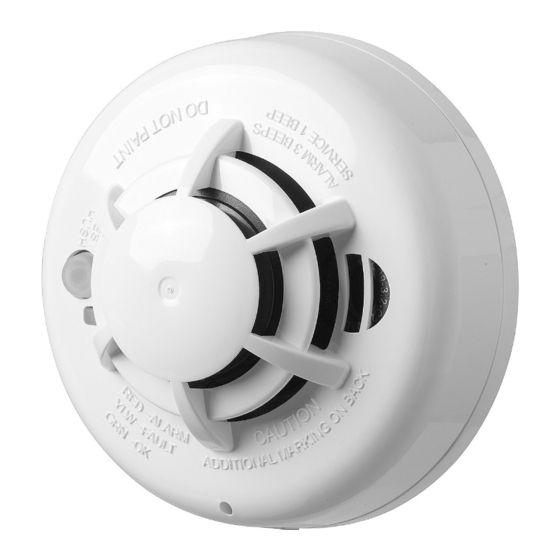
SMD-429 PG2 Series Wireless Smoke and Heat Detector
Installation and Operating Instructions
Read this instruction sheet thoroughly before installation and use of the SMD-429 PG2
Introduction
The SMD- 429 PG2 is a wireless photoelectric smoke and heat detector with a fixed tem-
perature and rate of rise heat detector, and an internal piezoelectric alarm.
Three versions are available: a 915 MHz for US version (UL) and Canadian version (ULC), a
433 MHz and 868 MHz for International version (EU) and a 433 MHz for Australian version
(AUS).
Compatible Devices
The smoke detector is compatible with Visonic Control Panels and Power G receivers.
HUSH/TEST BUTTON
Operation
Approximately every 7 to 8 seconds the unit tests for a smoke or heat alarm condition. During
this sequence the unit also performs self diagnostics, and checks for tampers and faults. During
normal operation the green LED flashes every 12 seconds and the sounder does not sound.
Smoke Alarm
The smoke detector alarms when the signal level exceeds the "alarm" threshold and auto-
matically restores when the signal level falls below the alarm "restore" threshold. During an
alarm the LED flashes once per second and the sounder sounds the evacuation temporal pat-
tern.
Alarm Silencing
This smoke alarm is provided with an automatically resettable alarm silencing feature. When the
sensor is in alarm, press the Test/Silence/Reset button to silence the local annunciation of the
alarm and transmit an alarm restore event to the control panel. The LED flashes every 8
seconds for up to 10 minutes, to indicate the alarm has been silenced.
The flashing LED stops when the unit returns to normal operation. The alarm silence feature
has a fixed time setting that desensitizes the smoke alarm for 8 minutes.
Alarm silencing does not disable the smoke alarm but rather reduces its smoke sensitivity. Fol-
lowing the silenced period the smoke alarm restores automatically to its intended operation. If
smoke around the unit is dense enough to suggest a potentially dangerous situation, it remains
in alarm, or may return to the alarm state quickly.
Detector Trouble
When the detector has a general fault, the yellow LED blinks once every four seconds and
there is a chirp every 48 seconds. After 12 hours, the panel will display a loss of supervision
message.
Status
LEDs
Normal
Green flash every 12 seconds
Heat Alarm Red flash every 1 second
Heat Test
Red flash every 1 second
Smoke
Red flash every 1 second
Alarm
Smoke Test Red flash every 1 second
Test Alarm Red flash every 1 second
Detector
Yellow flash every 4 seconds
Trouble
Sounder
(do not pulse the sounder and
LED concurrently)
Off
ANSI S3.41 temporal 3
ANSI S3.41 temporal 3
ANSI S3.41 temporal 3
(press button to hush for 5-10 minutes)
ANSI S3.41 temporal 3
(press button to hush for 5-10 minutes)
ANSI S3.41 temporal 3
One chirp every 48 seconds
Advertisement
Table of Contents

Subscribe to Our Youtube Channel
Related Manuals for Visonic SMD-429 PG2 Series


Summary of Contents for Visonic SMD-429 PG2 Series
-
Page 1: Compatible Devices
The smoke detector is compatible with Visonic Control Panels and Power G receivers. Detector Trouble When the detector has a general fault, the yellow LED blinks once every four seconds and there is a chirp every 48 seconds. - Page 2 Alarm / Alarm Restore - (heat or smoke alarm). Transmitted at time of occurrence. Sounder NOTE: During an alarm condition, the detector sends an alarm event to the control panel. Status LEDs (do not pulse the sounder and When the condition is restored, the detector sends an alarm restore event to the LED ...
-
Page 3: Installation Instructions
1. In all sleeping rooms and guest rooms. The SMD-429 PG2 Series wireless smoke detector shall be installed and used within an envir- 2. Outside of each separate dwelling unit sleeping area, within 6.4 m (21 ft) of any door to a onment that provides the pollution degree max 2 and over voltages category II in non- haz- sleeping room, the distance measured along a path of travel. - Page 4 100 mm (4 in.) minimum 100 mm (4 in.) minimum 3. Mounting Fit the detector inside the base by aligning it over the base. The detector's alignment notch should be slightly offset from the mounting base tamper release tab. Then turn the detector clockwise until it clicks into place.
-
Page 5: Household Fire Safety Audit
Household Fire Safety Audit Step Procedure 1. Are all electrical appliances and outlets in safe condition? Check for frayed cords, over- See the Installation Manual for the alarm system that the device is being enrolled on, to loaded lighting circuits, etc. If you are uncertain about the condition of your electrical appli- ensure that the proper steps are used. -
Page 6: Testing Your Smoke Detector
Make sure your fire warning system is operational by conducting weekly tests. If you are This is followed by 3 loud alarm beeps and at the same time the red LED flashes. Otherwise unsure about system operation, contact your smoke detector installer or dealer. the detector produces a warning signal, see the Alarm Indication table for details. -
Page 7: Specifications
This warranty shall apply to the Product only. All products, accessories or attachments of others used in Visonic Limited (the “Manufacturer") warrants this product only (the "Product") to the original purchaser only (the “Purchaser”) against defective conjunction with the Product, including batteries, shall be covered solely by their own warranty, if any. -
Page 8: End User License Agreement
Tyco determines. THIS EULA IS A LEGAL AGREEMENT BETWEEN YOU AND VISONIC LTD. (“TYCO”) AND GOVERNS YOUR USE OF THE SOFTWARE Subsequent EULA. Tyco may also supersede this EULA with a subsequent EULA pursuant to providing you with any future component, ACCOMPANYING THIS EULA, WHICH SOFTWARE INCLUDES COMPUTER SOFTWARE AND MAY INCLUDE MEDIA, PRINTED MATERIALS, release, upgrade or other modification or addition to the Software. ... -
Page 9: Regulatory Information
252.211-7015, or subparagraphs (a) through (d) of the Commercial Computer Software Restricted Rights at FAR 52.227-19, as applicable, or similar clauses in the NASA FAR Supplement. Contractor/manufacturer is Visonic Ltd., 24 Habarzel St., Tel-Aviv, Israel son fonctionnement normal. Les antennes utilisées pour ce produit ne doivent pas être situés ou exploités conjointement 69710.
Need help?
Do you have a question about the SMD-429 PG2 Series and is the answer not in the manual?
Questions and answers