Viking DEVDSC305 Installation Manual
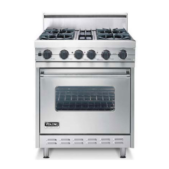
Freestanding gas ranges
Hide thumbs
Also See for DEVDSC305:
- Reference manual (28 pages) ,
- Installation manual (20 pages) ,
- Use and care manual (19 pages)
Table of Contents
Advertisement
Quick Links
Advertisement
Table of Contents

Related Manuals for Viking DEVDSC305


Summary of Contents for Viking DEVDSC305
- Page 1 Viking Installation Guide Freestanding Gas Ranges...
-
Page 2: Important: Please Read And Follow
WARNING •This range can tip. •Injury to persons could result. •Install anti-tip device packed with range. •See Installation Instructions WARNING IF THE INFORMATION IN THIS MANUAL IS NOT FOLLOWED EXACTLY, A FIRE OR EXPLOSION MAY RESULT CAUSING PROPERTY DAMAGE, PERSONAL INJURY, OR DEATH. -
Page 3: General Information
It is strongly recommended that a pallete or lift jack be used rather than tilting. NOTE: If legs are removed from range and range rests on a combustible surface, warranty and CSA certification are void. -
Page 4: Minimum Clearances
BASIC SPECIFICATIONS VGIC Description 30” W. Models Overall width 29 7/8” (75.9 cm) Overall height Base Height To top of: To top of spider grate - add 1 1/8” (2.9 cm) To top of 10” backguard - add 10” (25.4 cm) To top of island trim - To top of 6”... -
Page 5: Anti-Tip Stability Device Installation Instructions
1. The anti-tip bracket is to be attached to the rear wall as shown. The dimension for the bracket location from the floor is to be determined after the range legs have been adjusted to the proper installation height shown in the installation instructions and the range has been leveled. -
Page 6: Proximity To Side Cabinet Installation
36” (91.4 cm) high countertop. 4. Wall cabinets above the range must be a minimum of 36” (91.4 cm) for open top burner units and 42” (106.7 cm) for sealed top burner units above the range cooking surface for the full width of the range. This minimum height requirement does not apply if a rangehood is installed over the cooking surface. -
Page 7: Wood/Composite Overlay Installation
WOOD/COMPOSITE OVERLAY INSTALLATION (Including Custom Ventilator Installation) The bottom of a standard hood should be 30” (76.2 cm) min. to 36” (91.4 cm) max. above the countertop. This would typically result in the bottom of the hood being 66” (167.6 cm) to 72” (182.9 cm) above the floor. Refer to the rangehood installation instructions for additional information. - Page 8 1. If the floor is smooth and level, level the unit with the screw thread of the legs. Set the high corner of the range so that the the top of the grate support is 3/8”...
-
Page 9: Gas Connection
All gas connections must be made according to national and local codes. This gas supply (service) line must be the same size or greater than the inlet line of the appliance. This range uses an ISO7 or ISO128 inlet. The inlet depends on the end users national and local codes. - Page 10 GAS/ELECTRICAL CONNECTION DIAGRAM NOTE: If the gas supply is installed through the rear wall, the location MUST be 31 1/16” (78.9 cm) above the floor and 2 3/4” (7.0 cm) from the left hand side (when facing the unit) or within a maximum of 4 3/8” (11.1 cm) above the floor as specified in the drawing above.
-
Page 11: Flame Height
OVEN TUBULAR GAS BURNER ADJUSTMENT (See Illustration #1) Check the gas supply, and set the regulator to proper supply of gas. A properly adjusted burner should be stable and quiet. The flame should have a sharp, well defined blue inner cone with no yellow tipping. The flame should also be stable and uniform with no flames lifting off the burner ports. -
Page 12: Surface Burner Adjustments
SURFACE BURNER ADJUSTMENTS (For Open Surface Burners) To gain access to the surface burner adjustments: 1. Remove the grates, burner caps, bowls and grate supports. 2. Located the air shutter (A) and loosen the screw (B) that holds the air shutter in place. 3. -
Page 13: Grill/Griddle Burner Adjustment
GRILL/GRIDDLE BURNER ADJUSTMENT Grill (Illustration 3) 1. The grill burner orifice and air shutter are located beneath the front end of the grill assembly. To gain access to the adjsutments, remove the grill grate, flavor generator plates, grate support, and the burner shield. - Page 14 DSI SPARK MODULE SPECIFICATIONS Power Requirements Input Voltage range (L1-N) 102 to 132 VAC, 60/50 Hz 135 mA current typical Control Outputs Bake or Broil Burner Coil Pull-in pulse 54VDC + 10% @ 250mA Coil Hold-in 36 mA minimum Life Requirements...
- Page 15 Description of Operation (con’t) Lockout The control will lockout if any self-checks fail during normal operation. Also, the control will lockout if it failed to ignite gas after the selected number of ignition attempts or ignition recycles. In lockout the valve and ignition means are turned off.
- Page 16 TIMING DIAGRAM: NORMAL IGNITION CYCLE TIMING DIAGRAM: POWER UP CYCLE - IGNITION, FLAME LOSS Flame Sense Current Measurement Local Sense: Connect a DC Micro-amp meter in series with the high voltage lead and the spark electode wire as shown. Push switch to read current after flame is established and the spark output is de-energized. LOCAL SENSING: CONNECT DC MICRO-AMP METER IN SERIES WITH HIGH VOLTAGE LEAD AS SHOWN PUSH SWITCH TO READ CURRENT AFTER FLAME IS ESTABLISHED AND SPARKING CEASES...
-
Page 17: Replacement Parts
When adjustments are required, contact your dealer/installer for corrections. If assistance is not available, contact Viking Range Corporation Preferred Service for the nearest authorized service agent at (888) 845-4641. All corrections to installation are the responsibility of the dealer/installer or end user. - Page 20 Viking Range Corporation 111 Front Street Greenwood, Mississippi 38930 USA (662) 455-1200 For product information, call 1-888-VIKING1 (845-4641) or visit the Viking Web site at vikingrange.com F20466A (061907J)
Need help?
Do you have a question about the DEVDSC305 and is the answer not in the manual?
Questions and answers