Table of Contents
Advertisement
Quick Links
Advertisement
Table of Contents

Subscribe to Our Youtube Channel
Related Manuals for Nouvag MD 30


Summary of Contents for Nouvag MD 30
- Page 1 Operation manual MD 30 Motor System for Implantology and Oral Surgery...
-
Page 3: Table Of Contents
Electronic motor 21 9 Maintenance 25 Replacing the control unit fuse Safety inspections (STI) 10 Malfunctions and troubleshooting 11 Spare parts list with order numbers 12 Information on disposal 29 MD 30, Operating Instructions, REF 31686, V49/20... -
Page 4: Product Description
800 – 1060 hPa Warranty coverage Purchasing the MD 30 entitles you to a 1-year warranty. If you return the warranty card for registration with- in four weeks of the date of purchase, warranty coverage will be extended for a further 6 months. -
Page 5: Explanation Of Symbols
Date of expiry CE symbol with notified body Indication of the pump flow direction Dangerous goods Aerosol spray: Dangerous goods Aerosol spray: Environmentally hazardous Extremely flammable NouvaClean/NouvaOil NouvaClean/NouvaOil Dangerous goods Aerosol spray: Warning NouvaClean/NouvaOil MD 30, Operating Instructions, REF 31686, V49/20... -
Page 6: Safety Information
Every use of the MD 30 different to the product description defined in chapter “Intended use and opera- tion”, causes risks for patients and trained personnel. If physical examinations and therapies are carried out without use of the devices then the devices must be removed from the place of treatment. -
Page 7: Modification And Misuse
The warranty is no longer valid. Use of the MD 30 outside the indications described in Section 1.1 is prohibited. The user or operator is solely responsible for any such use. -
Page 8: Scope Of Delivery
Spray adapter for NouvaOil spray for the care of electronic motors -------------------------------------- 1 31686 User Manual MD 30 on CD-ROM ----------------------------------------------------------------------------------- 1 In line with regulations pertaining to hazardous materials, the following items are not delivered with the control unit and must be ordered separately:... -
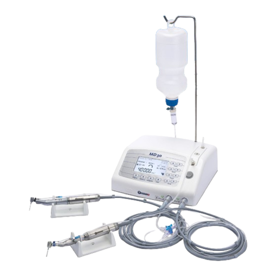
Page 9: Device Overview
22. Power entry module with fuse compartment 10. Operation panel 23. Spray adapter for the lubrication of the electronic motor 11. Release key for tubing set bracket (REF 19584) 12. Display 13. Peristaltic pump Rear view 20 21 MD 30, Operating Instructions, REF 31686, V49/20... -
Page 10: Startup
Device setup • Installation layout • Place the MD 30 and all required accessories and instruments on an even, non-slip surface and make sure you have good access to all controls. • The installation of the device in close proximity to other devices is prohibited due to EMC – please see section 3.1 and the manufacturer’s EMC declaration in the appendix of this manual. -
Page 11: Device Preparation
It indicates the flow direction of the cooling liquid. Do not regulate the amount of irrigation fluid using the roller clamp on the tubing set; with the MD 30, this is regulated instead using the integrated pump. For this reason, make sure to open the roller clamp as far as it will go (please refer to 7.4.5 Setting the pump supply quantity). -
Page 12: Assembly Of External Irrigation System
F) Attach grey clip with tube set to the cable of the motor G) Ready to use drill unit with attached external cooling system. If required, secure additional clips to the motor cable. MD 30, Operating Instructions, REF 31686, V49/20... -
Page 13: Assembly Of Internal And External Irrigation System (Optional)
L) Tube set routing with Y-connector for internal and external cooling of the instrument. Essential accessories for internal cooling: REF 1777 REF 1873 Y-connector Motor cable clips REF 1773 16 cm connection tubes MD 30, Operating Instructions, REF 31686, V49/20... -
Page 14: Operation
“▼”: reduces the maximum supply quantity By pressing both “Pump” keys at the same time “Pump ▲ + ▼” the pump will be put on call, pressing again will switch it off. MD 30, Operating Instructions, REF 31686, V49/20... -
Page 15: Overview: Standard Display
Bar graph providing a graphical representation of the current torque. All bars active means max. torque reached. The pump does not begin to operate until the motor is activated by pressing the pedal. MD 30, Operating Instructions, REF 31686, V49/20... -
Page 16: Adjusting The Programs
Menu (refer to “7.8 configuration menu, Parameter Level 1, Handpiece existing”). As a result by pressing the button «Handpiece» not all handpieces will be recalled, but only those that belong to the assortment. MD 30, Operating Instructions, REF 31686, V49/20... -
Page 17: Step 2: Calibrating Handpieces
Using the pedal, the speed can be varied from the minimum speed up to the maximum speed as set. Setting the speed: Press the «Speed» keys “▲” to increase or “▼” to decrease the maximum speed. When key is pressed con- stantly the speeds will be shown in fast forward mode. MD 30, Operating Instructions, REF 31686, V49/20... -
Page 18: Step 4: Setting The Torque
Menu (refer to «7.8 Configuration Menu, Parameter level 2, Pump»). To activate or deactivate the pump, press both “Pump” keys at the same time, “Pump + ”, or use the foot switch MD 30, Operating Instructions, REF 31686, V49/20... -
Page 19: Torque Limit Function, Al Mode (Automatic Limiter)
12000 2800 2100 1200 700 Storing various programs With the MD 30, up to 10 different settings can be set per motor as fixed program (program 1 to program 10). Which program is currently active is shown on the display. -
Page 20: Configuration Menu
• To cancel the setting, press the “Enter” button only briefly. The setting jumps back to the former value. 3. Exit the configuration menu: • To exit the configuration menu press “Enter” for 3 seconds, until a long tone is emitted. MD 30, Operating Instructions, REF 31686, V49/20... - Page 21 20 : 1 yes/no Handpiece existing/HP 08 32 : 1 yes/no Handpiece existing/HP 09 70 : 1 yes/no Handpiece existing/HP 10 Micro Saw yes/no Handpiece existing/HP 11 Mucotome yes/no Handpiece existing/HP 12 Kirschner yes/no MD 30, Operating Instructions, REF 31686, V49/20...
- Page 22 20 – 100% 100% Set the range where section 3 is active. The MD 30 can recognize the type of a plugged-in motor. This enables the adaption of future motors and their safe operation. MD 30, Operating Instructions, REF 31686, V49/20...
- Page 23 ▲ + ▼”). For this procedure you have to be out of the Configuration Menu. Exit the configuration menu: • To exit the configuration menu press “Enter” for 3 seconds, until a long tone is emitted. MD 30, Operating Instructions, REF 31686, V49/20...
-
Page 24: Operation Using The Vario Pedal
(speed as set on the control unit) For safety reasons, the unit can only be operated by pedal. The following handpieces run only with one specific speed, it cannot be changed. ● Micro saws Mucotome ● MD 30, Operating Instructions, REF 31686, V49/20... -
Page 25: Functional Check
7.10 Functional check Prior to MD 30 startup or use of accessory equipment, the user must always ensure that each individual component is in good working order, free from defects, and is clean, sterile and operational. All inscriptions on the device and its accessories must be readable and there must be no loose parts in the device. Once the device is switched on, the most recent settings entered appear on the display and the green LED for motor 1 lights up. -
Page 26: Cleaning, Disinfection And Sterilization
Do not use tubing sets when packaging is already open or damaged! Do not use tubing sets when expiry date has passed. Use only Nouvag tubing sets with REF 1706 and REF 6025! Sterility cannot be guaranteed by reusing and re-sterilization of tubing sets. The characteristics of the material change in a manner that can result in failure of the system. -
Page 27: Maintenance
The STI (Safety technical inspection) for the MD 30 shall be executed every 2 years by authorized experts. Results shall be documented. -
Page 28: Malfunctions And Troubleshooting
If the display is illuminated red by an error warning, the error code can be found on the next page in this user manual under “MD 30 Error messages on display”. MD 30, Operating Instructions, REF 31686, V49/20... - Page 29 System Error Send Control Unit to Service Center. Storing factory settings/ Message while default values of parameters and programs are saved to the MD 30 dongle. User Config & Program Storing factory settings/ Message while default values of programs are stored.
- Page 30 NouDongle was plugged in. The red highlighted error messages are also illuminated red on the control device display. The other messages are for information and do not require any action by the user. MD 30, Operating Instructions, REF 31686, V49/20...
-
Page 31: Spare Parts List With Order Numbers
Aerosol sprays such as NouvaClean and NouvaOil are hazardous goods that must be declared accordingly when shipping. Nouvag AG / Nouvag GmbH is not liable if this regulation is not observed. Defective or even damaged aerosol containers must not be returned to Nouvag AG / Nouvag GmbH, but must be dis- posed of locally and properly. - Page 33 Anhang Appendix Appendice Appendice Apéndice Appendix Aneks Apendix Appendix Függelék...
- Page 36 Electromagnetic compatibility (EMC) Remark: The Product subsequently referred to herein always denotes the MD 30. Changes or modifications to this product not expressly approved by the manufacturer may result in increased emissions or decreased immunity performance of the product and could cause EMC issues with this or other equipment. This product is designed and tested to comply with applicable regulations regarding EMC and shall be installed and put into service according to the EMC information stated as follows.
- Page 37 IEC 61000-4-11 is recommended that the Product be powered 70 % U ; for 25/30 cycles 70 % U ; for 25/30 cycles from an uninterruptible power supply or a battery. 0 % U for 5 sec 0 % U for 5 sec Power frequency 30 A/m...
- Page 38 Electromagnetic immunity against high-frequency wireless communication devices Test frequency Frequency Communication Modulation Maximum distance Test level band service Performance Pulse modulation 380 to 390 TETRA 400 18 Hz GMRS 460, 430 to 470 ± 5 kHz Hub FRS 460 1 kHz Sinus Pulse modulation 704 to 787 LTE Band 13, 17...
- Page 39 Phone +49 7531 1290–0 • Fax +49 7531 1290–12 info–de@nouvag.com • www.nouvag.com Nouvag USA • 5986 Highway 144 • Walnut Springs, Texas 7690 • USA Phone +1 (817) 887 9814 • Fax +1 (817) 887 9817 • Toll free (800) 673 7427 www.nouvagusa.com •...
Need help?
Do you have a question about the MD 30 and is the answer not in the manual?
Questions and answers