Table of Contents
Advertisement
Quick Links
Advertisement
Table of Contents

Subscribe to Our Youtube Channel
Related Manuals for Citizen CTE351XEEBX


Summary of Contents for Citizen CTE351XEEBX
- Page 1 LINE THERMAL PRINTER MODEL CT-E351 User’s Manual...
- Page 2 WEEE MARK If you want to dispose of this product, do not mix it with general household waste. There is a separate collection systems for used electronics products in accordance with legislation under the WEEE Directive (Directive 2002/96/EC) and is effective only within European Union. Wenn Sie dieses Produkt entsorgen wollen, dann tun Sie dies bitte nicht zusammen mit dem Haushaltsmüll.
- Page 3 (2011/65/EU) Full text of the EU declaration of conformity is available at the following internet address: http://www.citizen-systems.co.jp/english/support/download/printer/others/eu_doc/ IMPORTANT: This equipment generates, uses, and can radiate radio frequency- energy and if not installed and used in accordance with the instruction manual, maycause interference to radio communications.
- Page 4 Note that Citizen Systems is not responsible for any operation results regardless of omissions, errors, or misprints in this manual. Note that Citizen Systems is not responsible for any trouble caused as a result of using options or consumables that are not specified in this manual.
- Page 5 SAFETY PRECAUTIONS ...WHICH SHOULD BE STRICTLY OBSERVED Before using this product for the first time, carefully read these SAFETY PRECAU- TIONS. Improper handling may result in accidents (fire, electric shock or injury). In order to prevent injury to operators, third parties, or damage to property, special warning symbols are used in the User’s Manual to indicate important items to be strictly observed.
- Page 6 Should it occur, immediately turn the printer off, unplug it from the supply outlet, and call your local Citizen Systems dealer. Do not handle the printer in the following ways: Do not subject the printer to strong impacts or hard jolts (e.g., being stepped on, dropped or struck).
- Page 7 CAUTION Do not use the printer under the following conditions. Avoid locations subject to vibration or instability. Avoid locations where the printer is not level. Ÿ The printer may fall and cause an injury. Ÿ The quality of printing may deteriorate. ...
- Page 8 Ÿ Neglecting these cautions may cause wires or insulation to break, which could result in electric leakage, electric shock, or printer failure. If the power cord sustains damage, contact your Citizen Systems dealer. Do not leave things around the electric outlet.
- Page 9 CAUTION Caution label is attached in the position shown in the following figure. Carefully read the handling precautions before using the printer. These labels indicate that the head becomes hot, so touching it may cause burns, and touching the auto cutter when opening the paper cover may cause cuts on hands.
- Page 10 Do not touch any of the moving parts (e.g., paper cutter, gears, active electric parts) while the printer is working. In case of trouble do not attempt to repair the printer. Ask Citizen Systems ser- vice for repair.
-
Page 11: Table Of Contents
THE TABLE OF CONTENTS 1. GENERAL OUTLINE ..............12 1.1 Features .................... 12 1.2 Unpacking ..................13 1.3 Model Classification ................14 1.4 Basic Specifications ................14 2. EXPLANATION OF PRINTER PARTS ...........16 2.1 Printer Appearance ................16 2.2 Inside the Paper Cover ..............18 2.3 Other Built-in Functions .............. -
Page 12: General Outline
1. GENERAL OUTLINE The CT-E351 line thermal printer series is designed for use with a broad array of termi- nal equipment including data, POS, and kitchen terminals. These printers have extensive features so they can be used in a wide range of applica- tions. -
Page 13: Unpacking
1.2 Unpacking Make sure the following items are included with your printer. QUAN- NAME ILLUSTRATION TITY Printer AC Adapter (37AD5) AC power cord Partition Cable clamp Sample paper roll 1 roll Quick Start Guide — —... -
Page 14: Model Classification
1.3 Model Classification Model numbers indicate printer features according to the following system. CT - E351 RS E - BK 1. Model name 2. Interface RS: USB + serial ET: Ethernet+USB 3. Market U: North America E: Europe 4. Body case color WH: Pure white BK: Black Contact us in advance for special combinations, some of which may not be available. - Page 15 Item Specifications Line spacing 4.25 mm (1/6 inch) (Variable by command) Roll paper: 80 mm x max. φ83 mm Paper roll Paper thickness: 53 to 85 μm (paper roll inner diameter 12 mm / outer diameter 18 Interface USB + serial / Ethernet + USB Cash drawer kick-out Supports 2 cash drawers Input buffer...
-
Page 16: Explanation Of Printer Parts
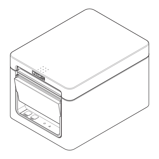
2. EXPLANATION OF PRINTER PARTS 2.1 Printer Appearance Names of parts 1. Paper cover Open to load paper. Also open to clear a cutter error. * The paper cover cannot be used for manual cutting. Refer to 4.2 Clearing a Cutter Error 2. - Page 17 Operation panel Two LEDs and two keys are placed on the operation panel. LED name Description Turns on when the power is turned on and turns off when the power is POWER LED turned off. Flashes when a memory error occurs and when data is being received. Flashes when the print head is hot, when the paper cover is open, ERROR LED when a cutter error occurs, and so on.
-
Page 18: Inside The Paper Cover
2.2 Inside the Paper Cover 1. Print head (thermal) Prints characters and graphic data on paper (paper rolls). 2. Paper end (PE) sensor Detects when there is no paper. Printing stops when this sensor detects there is no paper. 3. Platen Feeds the paper. -
Page 19: Other Built-In Functions
2.3 Other Built-in Functions Buzzer Buzzes when errors occur or when operations or command operations are performed. Refer to 4.5 Error Indications User memory You can save user-defined logo and character data in this memory. Data remains stored in this memory even if the printer is turned off. For information on how to save data, refer to the Command Reference. - Page 20 CAUTION Remove the partially cut paper before performing back feed for starting printing. The cut paper may be torn off in the next printing process, which may cause a problem. Auto side shift (MSW8-6) This function dissipates heat load during frequent heat generation by a vertical ruled line or other specific head heating element.
-
Page 21: Setup
3. SETUP 3.1 Connecting the AC Power Cord Turn off the power. Connect the power connector to the AC adapter cable connector. Next, connect the AC power cord to the AC inlet, and insert the plug into an electric outlet. 1. -
Page 22: Connecting Interface Cables
3.2 Connecting Interface Cables Turn off the power. Orient the interface cable correctly and insert it into the interface connector. USB + serial Ethernet + USB CAUTION When disconnecting the cable, always hold the connector. Be careful not to insert the USB cable into the cash drawer kick-out connector. ... -
Page 23: Ethernet (Lan) Interface
3.3 Ethernet (LAN) Interface The following describes an overview of the Ethernet (LAN) interface. For details on this function, refer to a separate manual. Note that the Ethernet (LAN) interface is not available in the USB + serial model. Panel button operation The function of the panel button is as follows. - Page 24 1. Network transmission speed Transmission speed LED (green) 100 Mbps 10 Mbps/Not connected Unlit 2. Network status Status LED (yellow) Connected Not connected Unlit Data transmission in Flashing progress Changing network settings You can use a web browser to access a special settings page to check and change board settings.
- Page 25 Press the [Change Settings] button to enter the following Change Settings screen. For details, refer to a separate manual. — —...
-
Page 26: Connecting The Cash Drawer
3.4 Connecting the Cash Drawer Turn off the power. Confirm the orientation of the cash drawer kick-out cable connector and connect it to the cash drawer kick-out connector at the back of the printer. Remove the screw for the ground wire. Screw the cash drawer’s ground wire to the body of the printer. - Page 27 (2) Electric characteristics 1) Drive voltage: 24 VDC 2) Drive current: Approx. 1 A max. (not to exceed 510 ms.) 3) DRSW signal: Signal levels: “L” = 0 to 0.5 V, “H” = 3 to 5 V (3) DRSW signal Status can be tested by commands.
-
Page 28: Precautions For Installing The Printer
3.5 Precautions for Installing the Printer This printer can only be positioned horizontally. It cannot be positioned vertically or on a wall. Horizontal position Vertical position CAUTION Do not use the printer under the following conditions. Avoid locations subject to vibration or instability. ... -
Page 29: Loading Paper
3.6 Loading Paper Turn on the power. Flip up the cover open lever to open the paper cover. CAUTION When pressing up on the lever, take care that you do not pinch your fingers in the gap above the top of the lever. Load the paper roll so that the printable side of the paper is facing up, as shown by arrow A. - Page 30 CAUTION When opening the paper cover, be careful not to touch the entrance of the blade of the auto cutter. The print head is very hot immediately after printing. Be careful not to touch it with your hands. ...
-
Page 31: 58-Mm Width Roll Paper Partition
3.7 58-mm Width Roll Paper Partition Turn off the power. Flip up the cover open lever to open the paper cover. Mount the supplied partition to the groove. When using the 80-mm width roll paper, remove the partition. Change the print area width while referring to “Manual Settings for the Memory Switch- es”... -
Page 32: Setting The Long Life Printing (Llp) Function
3.8 Setting the Long Life Printing (LLP) Function It can extend the abrasion life of the head-resistant by reducing the pressure to press the print head against the paper. The Long Life Printing (LLP) function can be enabled by changing the position of the projection switch inside the paper cover. -
Page 33: Precautions For Creating Applications And Practical Operations
If this is the case, try using a cable with ferrite cores on both ends, which are very ef- fective at eliminating EMI. 3.10 Download Site for Various Electronic Files You can view support information and download the latest documents, drivers, utilities, etc. from the following site. http://www.citizen-systems.co.jp/support/download/printer/ct-e351/ — —... -
Page 34: Maintenance And Troubleshooting
4. MAINTENANCE AND TROUBLESHOOTING 4.1 Periodic Cleaning A dirty print head or platen may reduce printing quality or cause malfunctions. We rec- ommend cleaning the printer periodically (every 2 to 3 months) as shown below. Turn off the power. Flip up the cover open lever to open the paper cover. Wait a few minutes until the print head cools. -
Page 35: Clearing A Cutter Error
4.2 Clearing a Cutter Error If the auto cutter stops during the auto cutter operation with the blade of the auto cutter in the open position due to foreign matter entering, paper jamming, etc., the ERROR LED flashes. When a cutter error occurs, resolve the cutter error with the following procedure. Turn off printer power. -
Page 36: Self Test
4.3 Self Test You can use self test to check for printer problems. Performing a self test operation While paper is loaded, press and hold the FEED button and turn on the power. Hold the FEED button down for about one second until the buzzer sounds. Release the button to start self test. -
Page 37: Hexadecimal Dump Printing
4.4 Hexadecimal Dump Printing Print received data in hexadecimal. If problems such as missing or duplicated data occur, this function allows you to check whether or not the printer is receiving data cor- rectly. How to do hexadecimal dump printing Load paper. -
Page 38: Error Indications
4.5 Error Indications Paper End If the paper ends, the ERROR LED lights and a buzzer sounds. Load a new paper roll. The buzzer may not sound depending on the memory switch setting. Cover Open If the cover is opened, the ERROR LED lights and a buzzer sounds. The buzzer may not sound depending on the memory switch setting. - Page 39 The status display for various messages is shown below. Status POWER LED (green) ERROR LED (red) Buzzer sound *3 Paper End Paper cover or front cover is open *1 Paper cover or front cover is open *2 Cutter Error Memory Error —...
-
Page 40: Paper Jams
4.6 Paper Jams Take care to avoid obstruction of the paper outlet and paper jamming around the outlet during printing. If paper cannot get out of the printer, it can roll up on the platen inside the printer and cause an error. If the paper wraps around the platen, open the paper cover and carefully pull the paper out. -
Page 41: Other
5. OTHER 5.1 External Views and Dimensions (Unit: mm) — —... -
Page 42: Printing Paper
5.2 Printing Paper Use the paper shown in the following table or paper of the same quality. Paper type Product name Recommended Nippon Paper TP50KR-2Y, TP50KJ-R thermal roll paper Oji Paper PD150R, PD160R, PD160R-63 Mitsubishi Paper Mills HP220AB-1, F230AA, P220AB Koehler KT48-FA (Unit: mm) Paper width 80... -
Page 43: Manual Setting Of Memory Switches
5.3 Manual Setting of Memory Switches Memory switches are used to set various printer settings. Memory switches can be set manually, or by utilities or commands. This section explains how to perform manual settings. For information on how to set the memory switches using commands, please refer to the Command Reference. - Page 44 Press the FEED button. A setting is printed each time the FEED button is pressed in order through the cycle. When the current settings are printed, the COVER LED lights. Press the FEED button until the setting you want is printed. Press the FEED button for at least two seconds.
- Page 45 The function of each memory switch is shown in the following table. (Shaded values are factory settings.) Switch no. Function MSW1-1 Power ON Info Valid Not Send MSW1-2 Buffer Size 4K bytes 45 bytes MSW1-3 Busy Condition Full/Err Full MSW1-4 Receive Error Print“?”...
- Page 46 Switch no. Function MSW5-1 Buzzer Valid Invalid MSW5-2 Line Pitch 1/360 1/406 MSW5-3 USB Mode Virtual COM Printer Class MSW5-4 Reserved Fixed — MSW5-5 Reserved Fixed — MSW5-6 Reserved Fixed — MSW5-7 Reserved Fixed — MSW5-8 Reserved Fixed — MSW6-1 Act.
- Page 47 Switch no. Function Initial setting Setting value MSW9-1 Code Page PC437 PC 437, Katakana, PC 850, PC 858, PC 860, PC 863, PC 865, PC 852, PC 866, PC 857, WPC1252, Space page, PC 864, ThaiCode11 1Pass, ThaiCode11 3Pass, ThaiCode18 1Pass, ThaiCode18 3Pass, TCVN-3 MSW9-2 Int’Char Set...
- Page 48 CT-E351_UM_100_5L PMC-1702 February 2017...
Need help?
Do you have a question about the CTE351XEEBX and is the answer not in the manual?
Questions and answers