Table of Contents
Advertisement
Quick Links
Advertisement
Table of Contents

Related Manuals for Citizen CT-S801 III


Summary of Contents for Citizen CT-S801 III
- Page 1 LINE THERMAL PRINTER MODEL CT-S801 Type III User’s Manual...
- Page 2 WEEE MARK If you want to dispose of this product, do not mix it with general household waste. There is a separate collection systems for used electronics products in accordance with legislation under the WEEE Directive and is effective only within European Union. Wenn Sie dieses Produkt entsorgen wollen, dann tun Sie dies bitte nicht zusammen mit dem Haushaltsmüll.
- Page 3 (2011/65/EU) Full text of the EU declaration of conformity is available at the following internet address: http://www.citizen-systems.co.jp/en/printer/download/eu_doc.html IMPORTANT: This equipment generates, uses, and can radiate radio frequency energy and if not installed and used in accordance with the instruction manual, may cause interference to radio communications.
- Page 4 If you find omissions, errors, or have questions, please contact your Citizen Systems dealer. If you find any pages missing or out of order, contact your Citizen Systems dealer for a replacement. NOTICE...
- Page 5 CITIZEN is a registered trademark of Citizen Watch Co., Ltd. Japan All other trademarks are the property of their respective owners. Citizen Systems use these trademarks in accordance with the license of relevant owners. Copyright ©2023 by CITIZEN SYSTEMS JAPAN CO., LTD.
- Page 6 SAFETY PRECAUTIONS ...WHICH SHOULD BE STRICTLY OBSERVED Before using this product for the first time, carefully read these SAFETY PRECAUTIONS. Improper handling may result in accidents (fire, electric shock or injury). In order to prevent injury to operators, third parties, or damage to property, special warning symbols are used in the User’s Manual to indicate important items to be strictly observed.
- Page 7 • Dropping a metallic foreign object into the printer, may cause printer failure, fire, or electric shock. Should it occur, immediately turn the printer off, unplug it from the supply outlet, and call your local Citizen Systems dealer. Do not handle the printer in the following ways: ...
- Page 8 CAUTION Do not use the printer under the following conditions. Avoid locations subject to vibration or instability. Avoid locations where the printer is not level. • The printer may fall and cause an injury. • The quality of printing may deteriorate. ...
- Page 9 • Neglecting these cautions may cause wires or insulation to break, which could result in electric leakage, electric shock, or printer failure. If the power cord sustains damage, contact your Citizen Systems dealer. Do not leave things around the electric outlet.
- Page 10 CAUTION Caution label is attached in the position shown in the following figure. Carefully read the handling precautions before using the printer. THIS LABEL INDICATES THE RISK OF BURNS DUE TO THE HIGH TEMPERATURE OF THE PRINT HEAD AND A RISK OF BEING CUT BY THE MANUAL AND AUTO CUTTERS WHILE THE PAPER COVER IS OPEN.
- Page 11 Do not touch any of the moving parts (e.g., paper cutter, gears, active electric parts) while the printer is working. In case of trouble do not attempt to repair the printer. Ask Citizen Systems service for repair. Be careful that the covers do not pinch your hands or fingers.
-
Page 12: Table Of Contents
THE TABLE OF CONTENTS 1. GENERAL OUTLINE ..............10 1.1 Features..................10 1.2 Unpacking..................11 1.3 Model Classification ..............11 1.4 Basic Specifications............... 12 2. EXPLANATION OF PRINTER PARTS ........14 2.1 Printer Appearance ................ 14 2.2 Inside the Paper Cover ..............17 2.3 Other Built-in Functions.............. -
Page 13: General Outline
1. GENERAL OUTLINE The CT-S801III line thermal printer series is designed for use with a broad array of terminal equipment including data, POS, and kitchen terminals. These printers have extensive features so they can be used in a wide range of applications. -
Page 14: Unpacking
HWX:Wireless LAN + Ethernet (USB C: China host function) + USB A: Asia/Oceania Certain combinations may not be available. Check with Citizen beforehand. Notes: *1: AC power cord, serial I/F screw, firmware and other specifications vary according to markets. — 11 —... -
Page 15: Basic Specifications
1.4 Basic Specifications Item Specifications Model CT-S801III Print method Line thermal dot print method Print width 80 mm/640 dots, 72 mm/576 dots, 64 mm/512 dots, 54.5 mm/436 dots, 54 mm/432 dots, 52.5 mm/420 dots, 48 mm/384 dots, 45 mm/360 dots, 48.75 mm/390 dots, 68.25 mm/546 dots 8 ×... - Page 16 *3: Characters appear small because the dimensions include a blank area surrounding each character. *4: The 37AD5 is the AC adapter packaged as an accessory with the CT-S801IIIA. The 37AD3 is the AC adapter built in to the CT-S801IIIS. *5: Compliant if the Citizen Systems AC adapter (37AD3/5) is used. — 13 —...
-
Page 17: Explanation Of Printer Parts
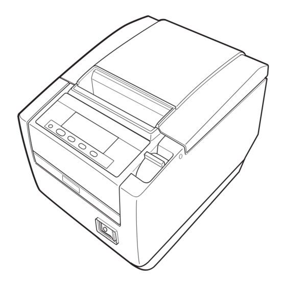
2. EXPLANATION OF PRINTER PARTS 2.1 Printer Appearance Names of parts Paper cover Cover open lever Operation panel Front cover Power switch Rear connectors Front cover release button (Front view) (Rear view) Paper cover Open to load paper. Cover open lever Use this lever to open the paper cover. - Page 18 Operation panel PAPER LOW LOCK icon Button 4 (MENU) Button 1 (FEED) Button 1 to Button 4 Examples are shown in the diagram of the LCD above on the right. LCD Indicates the printer’s status, button names, types of errors, and messages. ...
- Page 19 LCD in the vertical or wall mounted position You can change the memory switch settings to invert the LCD if the printer is used in a vertical position or installed on a wall. Inverted image Refer to 5.3 Manual Setting of Memory Switches Rear connectors Interface connector Power connector (AC adapter type)
-
Page 20: Inside The Paper Cover
2.2 Inside the Paper Cover Paper-end sensor (PE sensor) Paper damper Platen Auto cutter Button to change paper near-end sensor Manual cutter Print head (thermal) Paper near-end sensor (PNE sensor) Platen Feeds the paper. Do not remove the platen except to do maintenance. ... -
Page 21: Other Built-In Functions
2.3 Other Built-in Functions Buzzer Buzzes when errors occur or when operations or command operations are performed. Refer to 4.7 Error Messages User memory You can save user-defined logo and character data in this memory. Data remains stored in this memory even if the printer is turned off. For information on how to save data, refer to the Command Reference. - Page 22 Auto side shift (MSW8-6) This function dissipates heat load during frequent heat generation by a vertical ruled line or other specific head heating element. If no data is received within 15 seconds after each cut or print, the print position is automatically slid N* dots to the right.
-
Page 23: Setup
3. SETUP 3.1 Connecting the AC Power Cord Turn off the power. For the built-in power type printer, connect the AC power cord to the AC inlet, and insert the plug into an electric outlet. For the AC adapter type printer, connect the cable connector of the AC adapter to the power connector. -
Page 24: Serial Interface Board
3.2 Serial Interface Board Data can be exchanged by serial communication. Connecting the Interface Cable Turn off the power. Orient the cable correctly and insert it into the connector. Insert the other connector firmly into the interface port of the host computer. CAUTION ... - Page 25 Setting the DIP Switch on the Serial Interface Board Turn off the printer and unplug the power cord from the electric outlet. Remove the mounting screws of the serial interface board. Remove the serial interface board from the printer. Set the DIP switch according to the following table. DIP switch Serial interface board mounting screws CAUTION...
-
Page 26: Parallel Interface Port
3.3 Parallel Interface Port Data can be sent and received by parallel transmissions. Specifications Transmission method 8-bit parallel data Receive buffer size 16kByte Transmission mode Compatible mode/nibble mode/ECP mode Signal level IEEE 1284 compliant Connector Amphenol 36 pin Connecting Interface Cables Turn the power off. -
Page 27: Usb Interface Board
3.4 USB Interface Board Data can be exchanged by USB communication. Specifications Standard USB 2.0 specification-compliant Communication speed Supports 12 Mbps (Full-Speed) transfer Connector Type-B Compatible cable clamp GRBWS-0610E-V0 (KITAGAWA INDUSTRIES) or similar product Connecting the Interface Cable Turn off the power. Insert the cable clamp into the cable clamp mounting hole. - Page 28 Secure the interface cable with the cable clamp. Cable clamp Insert the other connector firmly into the interface port of the host computer. CAUTION When disconnecting the cable, always hold the connector. Place the interface cable so people do not trip on it. ...
-
Page 29: Bluetooth Interface Board
3.5 Bluetooth Interface Board Names of parts Status LED Switch Status LED The Bluetooth communication/connection/error status is indicated by this LED. Switch Control this interface board. Bluetooth status LED Status Description LED Status Detection Standing by for standby detection and (Discoverable) connection... - Page 30 Pairing operation You need to perform the operations below the first time you establish a Bluetooth connection for Bluetooth data communication. A: Detect Bluetooth devices B: Configure pairing settings A: Detecting Bluetooth devices Confirm that Bluetooth is enabled on the host PC before searching for Bluetooth devices.
- Page 31 Auto reconnection With iOS device Bluetooth communication, a connection between a paired iOS device and the printer is not automatically restored after it is lost. However, when auto reconnection is enabled, the printer tries to reconnect with an iOS device after two-way communication is enabled and automatically restores the connection.
-
Page 32: Ethernet (Lan)/Wireless Lan Interface Board
3.6 Ethernet (LAN)/Wireless LAN Interface Board This section provides an overview of the interface board. For details on this board, including explanations about the USB host function and XML peripheral device support,refer to the separate manual. Connecting the Interface Cable Turn off the power. - Page 33 Connecting the wireless LAN adapter Turn off the power. Connect the wireless LAN adapter to the connector. Panel button operation Board operations are performed using the panel button on the rear of the LAN board. Panel button 10/100BASE Panel button Panel button Ethernet Wireless LAN...
- Page 34 LED Functions The tables below explain how to interpret LED indications. 10/100BASE 10/100BASE Ethernet Wireless LAN Ethernet/Wireless LAN USB host model 1. Wired LAN transmission speed Transmission speed LED (green) 100 Mbps 10 Mbps/Not connected Unlit 2. Wired LAN connection/transmission status Connection status LED (yellow) Connected...
- Page 35 Web Manager The interface board has a Web Manager function that can be used to connect to the board with a web browser and change board settings. Starting up Web Manager Start up a web browser. In the address field, input the board's IP address and then press [Enter]. HOME Screen This is the Web manager home screen.
- Page 36 CONFIG Screen This will display the Login dialog box shown below. Log in as an administrator and then configure interface board settings. User Name Input a board administrator user name. (Initial setting: admin) Password Input the administrator user password. (Initial setting: admin) ...
-
Page 37: Connecting The Cash Drawer
3.7 Connecting the Cash Drawer Turn off the power. Confirm the orientation of the cash drawer kick-out cable connector and connect it to the cash drawer kick-out connector at the back of the printer. Remove the screw for the ground wire. Screw the cash drawer’s ground wire to the body of the printer. - Page 38 (1) Connector pin configuration Signal Function Frame ground DRAWER1 Cash drawer 1 drive signal DRSW Cash drawer switch input Cash drawer drive power supply DRAWER2 Cash drawer 2 drive signal Signal ground (common ground on circuits) (2) Electric characteristics Drive voltage: 24 VDC Drive current: Approx.
-
Page 39: Precautions For Installing The Printer
3.8 Precautions for Installing the Printer The printer can be used horizontally, vertically, or installed on a wall. However, the CT-S801IIIS (built-in power supply type) cannot be used vertically or installed on a wall. Use the optional stand for vertical applications, and the optional brackets for wall installations. -
Page 40: Partition For Paper Roll
3.9 Partition for Paper Roll Set the partition to the width of the paper roll you are loading. Turn off the power. Pull the cover open lever forward and open the paper cover. Set the partition in a slot that matches the size of the paper roll you are using. When using 83-mm wide roll paper, the partition must be removed. -
Page 41: Adjusting The Paper Near-End Sensor
3.10 Adjusting the Paper Near-end Sensor Change the settings of the paper near-end sensor to set the position at which the near-end of the paper is detected. Use a pointed object, such as a pen, to gently press the button to change the paper near-end sensor. -
Page 42: Loading Paper
3.11 Loading Paper Turn on the power. Pull the cover open lever forward and open the paper cover. Load the paper roll so that the printable side of the paper is facing down, as shown by arrow A. Pull a few cm of paper straight out in the direction of arrow B. Close the paper cover until you hear a click. -
Page 43: Download Site For Various Electronic Files
3.12 Download Site for Various Electronic Files You can view support information and download the latest documents, drivers, utilities, etc. from the following site. https://www.citizen-systems.co.jp/en/printer/download/#CT-S801III 3.13 Precautions for Creating Applications and Practical Operations If printing is done immediately after the paper is partially cut and torn off, the top of the next print out may be distorted. -
Page 44: Maintenance And Troubleshooting
MAINTENANCE AND TROUBLESHOOTING 4.1 Periodic Cleaning A dirty print head or platen may reduce printing quality or cause malfunctions. We recommend cleaning the printer periodically (every 2 to 3 months) as shown below. Turn off the power. Pull the cover open lever forward and open the paper cover. Wait a few minutes until the print head cools. -
Page 45: Clearing A Cutter Lock (1)
4.2 Clearing a Cutter Lock (1) The message “Cutter lock” may appear and the auto cutter blade may remain extended because a foreign object or paper jam is obstructing it. If “Cutter lock” is displayed, clear the locked cutter as shown below. Turn on the power. -
Page 46: Clearing A Cutter Lock (2)
The print head is hot immediately after printing. Do not touch it. Do not touch the print head with bare hands or metal objects. If the above procedure does not retract the auto cutter, contact your Citizen Systems dealer. — 43 —... -
Page 47: Function Test Mode
4.4 Function Test Mode Press and hold button 1 while turning on the printer to access the function test mode. Use button 3 ( ) to select a function, use button 4 ( ) to execute the function. Except for the self test and printing memory switch settings, all functions are for service personnel only. - Page 48 MSW3-7 MSW8-1 MSW6-2 Paper Character Manufacturer Model Full Col CBM1000 Print Character width space Print Mode Width Space CITIZEN CBM1000 58 mm — Auto Valid 432dots — linefeed 80 mm — Auto Valid 576dots — linefeed CT-S300 58 mm —...
- Page 49 DriverID Setting The driver ID in the models specified below can be changed. Each type of driver is available for each model. Normally, if a printer is replaced by a different model, the driver needs to be re- installed. When replacing one of the specified models, you can use the driver you have been using so far by changing the driver ID.
-
Page 50: Key Lock Function
4.5 Key Lock Function Press and hold the MENU button while the printer is running to be able to change the memory switch settings. Activate the key lock to prevent making changes by mistake. LOCK icon Button 3 Setting the key lock To set the key lock, press and hold button 3 (for at least three seconds). -
Page 51: Hexadecimal Dump Printing
4.6 Hexadecimal Dump Printing Print received data in hexadecimal. If problems such as missing or duplicated data occur, this function allows you to check whether or not the printer is receiving data correctly. How to do hexadecimal dump printing Load paper. While the paper cover is open, press and hold button 1 while turning the power on, and then close the paper cover. -
Page 52: Error Messages
4.7 Error Messages Paper end The end of the roll of paper is detected at two stages, paper near-end and paper-end. When paper near-end is detected, “PAPER LOW” appears on the LCD and the LED lights orange. Prepare a new paper roll. When paper-end is detected, “Paper end”... - Page 53 The situation during various errors is shown below. The LCD’s top line is the type of error, the bottom line is the remedy. Scroll through messages that are longer than 16 characters. Status Message Backlight Buzzer Paper near-end PAPER LOW Orange —...
-
Page 54: Paper Jams
4.8 Paper Jams Take care to avoid obstruction of the paper outlet and paper jamming around the outlet during printing. If paper cannot get out of the printer, it can roll up on the platen inside the printer and cause an error. If the paper wraps around the platen, open the paper cover and carefully pull the paper out. -
Page 55: Other
5. OTHER 5.1 External Views and Dimensions (Unit: mm) Built-in power supply type AC adapter type — 52 —... -
Page 56: Printing Paper
5.2 Printing Paper Use the paper shown in the following table or paper of the same quality. Paper type Product name Recommended Nippon Paper TP50KR-2Y, TP50KJ-R, TL69KS-LH, TF50KS-E2D thermal roll paper Oji Paper PD150R, PD160R, PD160R-63 Mitsubishi Paper Mills HP220AB-1, P220AB Koehler KT48-FA (Unit: mm) Paper width 58... -
Page 57: Manual Setting Of Memory Switches
5.3 Manual Setting of Memory Switches Memory switches are used to set various printer settings. The memory switches can be set manually (set by hand on the printer) or by commands. This section explains how to perform manual settings. Memory switch settings are done in memory switch setting mode or virtual DIP switch setting mode. - Page 58 Virtual DIP switch setting mode While paper is loaded, press and hold button 2 while turning the power on. Enter virtual DIP switch setting mode. • Press button 1( ) to select a memory switch number. (Switches cycle in the following order: MSW1 →...
- Page 59 The function of each memory switch is shown in the following table. (Shaded values are factory settings.) Switch no. Function MSW1-1 Power ON Info Valid Not Send MSW1-2 Buffer Size 4K bytes 45 bytes MSW1-3 Busy Condition Full/Err Full MSW1-4 Receive Error Print“?”...
- Page 60 Switch no. Function MSW6-1 Act. For Driver Invalid Valid MSW6-2 Character Space Invalid Valid MSW6-3 USB Power Save Invalid Valid MSW6-4 Reserved Fixed — MSW6-5 Reserved Fixed — MSW6-6 Reserved Fixed — MSW6-7 Reserved Fixed — MSW6-8 Reserved Fixed — Switch no.
- Page 61 Switch no. Function Initial setting Setting value MSW10-1 Print Density 100 % 70 %, 75 %, 80 %, 85 %, 90 %, 95 %, 100 %, 105 %, 110 %, 115 %, 120 %, 125 %, 130 %, 135 %, 140 % MSW10-2 Print Speed Level 9...
- Page 62 CT-S801III_UM_101EN A08706E-2310 DECEMBER 2023...
Need help?
Do you have a question about the CT-S801 III and is the answer not in the manual?
Questions and answers