Table of Contents
Advertisement
Quick Links
Advertisement
Table of Contents

Subscribe to Our Youtube Channel
Related Manuals for Weidmüller MultiMark


Summary of Contents for Weidmüller MultiMark
- Page 1 MultiMark THM MultiMark LPC Original operating instructions...
- Page 2 Manufacturer Weidmüller Interface GmbH & Co. KG Klingenbergstraße 26 32758 Detmold, Germany T +49 5231 14-0 F +49 5231 14-292083 www.weidmüller.com Document no. 2903400000 Revision 00/September 2022 2903400000/00/09.2022...
-
Page 3: Table Of Contents
Contents About this documentation Printing Synchronising the paper run Safety General safety notes Cleaning Intended use Cleaning the print roller Safety marking Cleaning the print head Personnel Cleaning the label light barrier Device description Troubleshooting Label printer Error display Mounting foot Printer error messages Applicator Printer problem solving... -
Page 4: About This Documentation
About this documentation The warnings in this documentation are designed accord- The situation-dependent warnings may contain the follow- ing to the severity of the danger. ing warning symbols: WARNING Icon Meaning Warning of dangerous electrical voltage Possible danger to life! Notes with the signal word “Warning”... -
Page 5: Safety
Safety 2.1 General safety notes 2.2 Intended use The labelling system is exclusively intended for printing Electricity and applying labels. The system may only be used to pro- cess materials approved for the labelling system, see the – The enclosures of all system components must not be Weidmüller online catalogue. -
Page 6: Safety Marking
Safety 2.3 Safety marking 2.4 Personnel Various warning symbols are attached to the labelling labelling system Only trained personnel may operate the system. These symbols must not be removed and must carry out maintenance work. They must also have read the always be legible. -
Page 7: Device Description
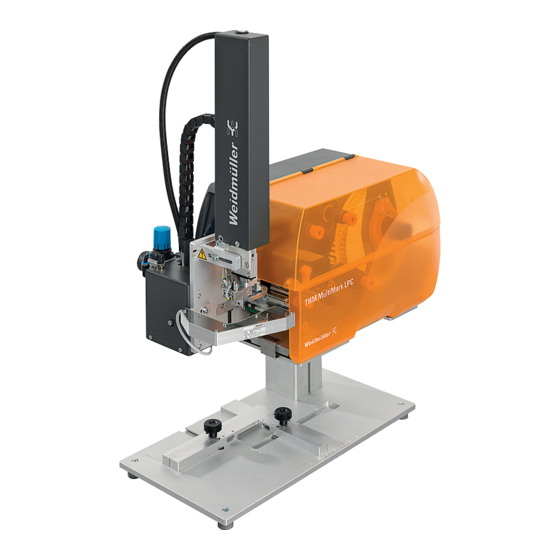
Device description Image 3.1 Overview of the labelling system Type plate Label printer Applicator with laser pointer Mounting foot Foot switch The printer is equipped with a wide-range power supply unit. Operation with a power supply of 230 V~/50 Hz or 115 V~/60 Hz is possible without any intervention in the device. -
Page 8: Label Printer
Device description 3.1 Label printer Image 3.3 Detail view of the printing assembly 11 Deflection for transfer foil 12 Head bracket with print head 13 Labelling light barrier 14 Hexagon key Image 3.2 Overview of the label printer 15 Lever to lock the print head 16 Print roller Cover 17 Adjusting knob for guides... -
Page 9: Mounting Foot
Device description 3.2 Mounting foot Image 3.4 Connections Image 3.5 Mounting foot 22 Mains switch Guide pins to position the printer on the mounting plate 23 Power socket Mounting plate 24 Slot for SD card Clip to fasten the printer on the mounting plate 25 USB interfaces for keyboard, scanner, USB stick, Bluetooth Profile adapter or service key... -
Page 10: Applicator
Device description 3.3 Applicator Image 3.6 Front and rear Spiral hose 10 Laser pointer Energy chain 11 Interface to the printer Compressed-air maintenance unit 12 Locking pins Knurled screw to fasten the applicator on the printer 13 Coupling for the compressed-air connection Main cylinder 14 Shut-off valve Cylinder assembly cover... -
Page 11: Technical Data
Device description 3.4 Technical data General data Ambient temperature Operation +5°C to 40°C Storage 0 °C to +60 °C Transport -25 °C to +60 °C Humidity Operation 10 % to 85 %, non-condensing Storage/transport 20 % to 85 %, non-condensing Max. -
Page 12: Type Plate
Device description 3.5 Type plate The following symbols are shown on the type plate Icon Meaning Neutral conductor fuse EU conformity Observe the disposal instructions Explanation of the serial number MLYYMM#### System identification Year Month #### Serial number Image 3.7 Type plate Product type Model Material number... -
Page 13: Unpacking And Installing Devices
Unpacking and installing devices 4.1 Fitting the printer on the mounting foot Select an installation site that meets the requirements, see chapter 2.1. Observe the following additional notes: – Stable base with a level and even surface (weight and dimensions, see technical data). –... -
Page 14: Fitting The Applicator On The Printer
Unpacking and installing devices 4.2 Fitting the applicator on the printer 4.3 Connecting the devices ► Make sure that the printer is disconnected from the The interfaces and connections are defined in the individu- mains. al component descriptions. ► Ensure that the printer is in a stable position. ►... -
Page 15: Operating Software
Operating software 5.1 Touch display The touch display lets you operate the printer’s operating software and execute the following functions: – Pause, continue or cancel print jobs – Set print parameters, e.g. heat energy of the print head, print speed, configuration of the interfaces, language and time (... - Page 16 Operating software For certain software or hardware configurations, additional The receipt of data from an interface is signalled by a icons are displayed on the start screen: falling drop The Save data stream function is active. All data received are saved in an .lbl file, see configura- tion instructions Prewarning end of foil: the residual diameter of the foil reel has fallen below a set value, see configuration instructions SD card installed...
-
Page 17: Menu Navigation
Operating software 5.3 Menu navigation Tapping on the gear takes you to the selection level of the operating menu. Tapping on the arrow takes you back one level. Tapping on the house takes you home. Home Selection level Parameter and func- tion level ►... -
Page 18: Setting Up The Printer
Setting up the printer 6.2 Placing labels in the print head CAUTION Danger of injury! When setting up the printer, work needs to be carried out with the cover open. ► Make sure that hair, loose clothing, jewel- lery and the like do not come into contact with exposed, rotating parts. -
Page 19: Inserting The Transfer Foil
Setting up the printer 6.3 Inserting the transfer foil ► Guide the transfer foil through the print assembly, see Image 6.4. ► Clean the print head before inserting the ► Fasten the start of the transfer foil on the transfer foil transfer foil, see chapter 8. -
Page 20: Adjusting The Transfer Foil Run
Setting up the printer 6.5 Adjusting the transfer foil run Creases in the transfer foil run can lead to errors in the print image. To avoid creasing, the transfer foil deflection (3) can be adjusted. It’s best to perform this adjustment during print operation. -
Page 21: Printing
Printing ATTENTION Incorrect handling can damage the print head! ► Do not touch the underside of the print head with your fingers or sharp objects. ► Make sure that the labels are not contaminated. ► Ensure the smooth surface of the labels. Rough labels act like an abrasive and reduce the service life of the print head. -
Page 22: Cleaning
Cleaning 8.2 Cleaning the print head To achieve a good, even print quality, the device should be cleaned monthly. During printing, contamination may collect on the print head and negatively affect the print image, e.g. due to con- DANGER trast differences or vertical strips. Regular cleaning makes an important contribution to preventing premature wear on Risk to life due to mains voltage. -
Page 23: Cleaning The Label Light Barrier
Cleaning 8.3 Cleaning the label light barrier The label sensors can be contaminated by paper dust. This can impair the detection of label start marks or print marks. ATTENTION The light barrier can be damaged! Hard or sharp objects can scratch the light barrier. Only use pure alcohol for cleaning. -
Page 24: Troubleshooting
Troubleshooting 9.1 Error display Any errors that occur are shown in the touch display. Image 9.1 Error displays The following options are available to continue operation: The print job is continued after eliminating the Repeat cause of the error. The current print job is cancelled. Cancel The label transport is re-synchronised. -
Page 25: Printer Error Messages
Troubleshooting 9.2 Printer error messages Error message Cause Corrective measure Locking system open The locking system at the deflection roller is not closed ► Close locking system in dispensing mode The locking system at the pull roller in the SQUIX MT is ► Close locking system not closed Barcode too big The barcode is too big for the assigned label area ►... - Page 26 Troubleshooting Error message Cause Corrective measure No label Multiple labels are missing on the label strip ► Repeat printing until the next label on the strip is detected The label format indicated in the software does not ► Cancel print job match the actual format ►...
-
Page 27: Printer Problem Solving
Troubleshooting 9.3 Printer problem solving Problem Cause Corrective measure Transfer foil creased Transfer foil deflection not calibrated ► Adjust the transfer foil run Head locking system not calibrated ► Adjust the head locking system Transfer foil too wide ► Use transfer foil that is just slightly wider than the label. -
Page 28: Sq Laser Applicator
10 SQ laser applicator 10.1 Configuration The applicator operation can be modified via parameter settings while maintaining the basic process. The key setting is selecting between the “Stamp” and “Blow” mode of operation. In addition, the applicator also have various modes relating to the print order and the application of the label during a labelling cycle. - Page 29 SQ laser applicator Parameter Meaning Default Device information Applicator information: Software version, overall and service counters for the number of labelling operations, error messages and cylinder cycles Reset service counter Reset the service counter shown in the device information (only accessible with Service Key) Cycle sequence Select the type of cyclical operation: Print/...
-
Page 30: Test Mode Without Print Job
SQ laser applicator 10.2 Test mode without print job 10.3 Test mode with pending print job This method lets you test the labelling operation with actual print data using the Cycle button in the display. ► Send a print job. The test mode runs in alternating half-cycles: ►... -
Page 31: Normal Operation
SQ laser applicator 10.4 Normal operation ATTENTION The printer can be damaged. The stamp and locking system can collide with each other. ► Swivel the printer’s locking system at the deflection roller before you start the labelling operation. ► Make sure that all connections are established before starting the labelling operation. -
Page 32: Applicator Error Messages
SQ laser applicator 10.5 Applicator error messages CAUTION Danger due to automatic start-up. After rectifying and acknowledging an error, the applicator immediately moves up to the home position. ► Do not reach into the stamp’s operating area. ► Keep hair, loose clothing and jewellery out of the operating area. - Page 33 SQ laser applicator Troubleshooting ► Rectify the error as described. ► To exit the error state, tap Next, Repeat or Cancel. The printer continues printing the next label. Next The incorrect label is reprinted (only for Suc- Repeat tion plate empty error). The print job is cancelled.
-
Page 34: Setting Up The Laser Pointer
11 Setting up the laser pointer ► Switch on the printer. laser pointer. ► Connect the compressed air supply to the applicator. Image 11.3 Align the laser Image 11.1 Switch on the laser pointer ► Calibrate the laser with screws A to D so that the lines ►... - Page 35 Setting up the laser pointer Image 11.5 Fasten the object ► Loosen the knurled screws (1) of the stops. ► Place the object on the object holder (2). ► Fasten the object by moving the stops (3). ► Tighten the knurled screws (3). 2903400000/00/09.2022...
-
Page 36: Decommissioning And Disposing Of The System
12 Decommissioning and disposing of the system 12.1 Decommissioning the system ► Switch off the system at the printer. ► Disconnect the mains plug. ► Remove the compressed-air hose from the compressed- air source. ► Remove the compressed-air hose from the compressed- air maintenance unit on the applicator. -
Page 37: Annex
13 Annex 2903400000/00/09.2022...
Need help?
Do you have a question about the MultiMark and is the answer not in the manual?
Questions and answers