Table of Contents
Advertisement
Quick Links
Advertisement
Table of Contents

Related Manuals for Weidmüller THM MultiMark TWIN


Summary of Contents for Weidmüller THM MultiMark TWIN
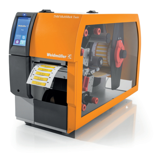
- Page 1 MultiMark THM MultiMark TWIN Thermal transfer printer Operating instructions...
- Page 2 Manufacturer Weidmüller Interface GmbH & Co. KG Klingenbergstraße 26 32758 Detmold, Germany T +49 5231 14-0 F +49 5231 14-292083 www.weidmüller.com Document no. 2967530000 Revision 00/June 2023 2967530000/00/06.2023...
-
Page 3: Table Of Contents
Contents About this documentation Cleaning Cleaning the print rollers Safety Cleaning the printheads General safety notes Cleaning the label light barrier Intended use Troubleshooting Personnel Error display Device description Error messages and troubleshooting Technical data Troubleshooting Type plate Decommissioning and disposing of the device Unpacking the device and putting it into operation 10.1 Decommissioning the device Connecting the computer or computer network... -
Page 4: About This Documentation
About this documentation The warnings in this documentation are designed accord- The situation-dependent warnings may contain the follow- ing to the severity of the danger. ing warning symbols: DANGER Icon Meaning Warning of dangerous electrical voltage Imminent risk to life! Notes with the signal word „DANGER“... -
Page 5: Safety
Safety 2.1 General safety notes 2.2 Intended use The printer is exclusively intended for printing labels. The Electricity printer may only be used to process materials approved for it, see the Weidmüller online catalogue. Any other use – The enclosure of the device must not be opened. or use above and beyond these instructions is considered –... -
Page 6: Device Description
Device description Figure 3.2 Device version with perforation cutter Figure 3.1 Overview of the printer “Device switched on” LED Display Peripheral interface Flap Cover Inside margin stop Outside margin stop Reel holder Top transfer ribbon unwinder 10 Top transfer ribbon winder 11 Print mechanism 12 Bottom transfer ribbon unwinder 13 Bottom transfer ribbon winder... - Page 7 Device description Figure 3.5 Connections Figure 3.3 Top print mechanism 33 Mains switch 15 Deflection for top transfer ribbon 34 Mains connection socket 16 Head bracket with top printhead 35 Slot for SD card 17 Locking system 36 2 USB host interfaces for keyboard, scanner, USB stick, USB 18 Pull roller WLAN adapter, USB Bluetooth adapter or external control panel 19 Top print roller...
-
Page 8: Technical Data
Device description 3.1 Technical data General data Ambient temperature Operation +5°C to 40°C Storage 0 °C to +60 °C Transport -25 °C to +60 °C Humidity Operation 10 % to 85 %, non-condensing Storage/transport 20 % to 85 %, non-condensing Max. -
Page 9: Type Plate
Device description 3.2 Type plate The following symbols are shown on the type plate. Icon Meaning Neutral conductor fuse EU conformity Observe the disposal instructions Explanation of the serial number MTYYMM#### System identification Year Month #### Serial number Figure 3.6 Type plate Product type Model Material number... -
Page 10: Unpacking The Device And Putting It Into Operation
Unpacking the device and putting it into operation Select an installation site that meets the requirements, see chapter 2.1. Observe the following additional notes: – Stable base with a level and even surface (weight and dimensions, see technical data). – Electricity connection easily accessible nearby –... -
Page 11: Operating Software
Operating software 5.1 Touch display Open the menu The touch display lets you operate the printer’s operating Pause or continue a print job software and execute the following functions: – Pause, continue or cancel print jobs Repeat last label – Control the stand-alone operation with memory device –... - Page 12 Operating software For certain software or hardware configurations, additional The receipt of data from an interface is signalled by a icons are displayed on the start screen: falling drop The Save data stream function is active. All data received are saved in an .lbl file, see configura- tion instructions Prewarning Out of ribbon: the residual diameter of the ribbon reel has fallen below a set value, see configura-...
-
Page 13: Menu Navigation
Operating software 5.3 Menu navigation Tapping on the gear takes you to the selection level of the operating menu. Tapping on the arrow takes you back one level. Tapping on the house takes you home. Home Selection level Parameter and func- tion level ►... -
Page 14: Setting Up The Printer
Setting up the printer 6.2 Positioning the material reel on the reel CAUTION holder Danger of injury! When setting up the printer, work needs to be carried out with the cover open. ► Make sure that hair, loose clothing, jewel- lery and the like do not come into contact with exposed, rotating parts. -
Page 15: Inserting Material Into The Print Mechanism
Setting up the printer 6.3 Inserting material into the print mecha- Only devices with perforation attachment: ► Feed the material between the perforation knives. nism ► Turn the lever (8) clockwise to lock the top printhead. ► Pull the locking bolt (4), press the locking system (1) down and lock it with the locking bolt. -
Page 16: Adjusting The Head Locking System
Setting up the printer 6.5 Adjusting the head locking system The printheads are pressed down by two plungers each that are positioned in the middle of the head bracket in the home position. This setting can be retained for most ap- plications. -
Page 17: Inserting The Transfer Ribbon
Setting up the printer 6.6 Inserting the transfer ribbon ► Clean the printhead before inserting the trans- fer ribbon, see chapter 8. Figure 6.9 Insert the transfer ribbon ► Turn the lever (6) counter-clockwise to release the top printhead. ► Slide the transfer ribbon reel (1) onto the unwinder (2) so that the colour coating on the ribbon points down dur- Figure 6.8 Transfer ribbon run ing unwinding. -
Page 18: Adjusting The Transfer Ribbon Run
Setting up the printer 6.7 Adjusting the transfer ribbon run ► Read the current setting on the scale (1) and note this down. Creases in the transfer ribbon run can lead to errors in the ► Turn the screw (2) and observe the behaviour of the rib- print image. -
Page 19: Printing
Printing 7.3 Avoiding material loss ATTENTION The print information for a section is applied to Incorrect handling can damage the printheads! the material at different times at two different lo- ► Do not touch the underside of the printheads with your cations in the material transport direction. -
Page 20: Avoiding Data Loss
Printing 7.4 Avoiding data loss When recoverable errors occur, the sections that were completed by the bottom printhead before the error but not completed by the top printhead are not repeated. The data from these sections is no longer available to the printer. ►... - Page 21 Cleaning 8.2 Cleaning the printheads To achieve a good, even print quality, the device should be cleaned monthly. During printing, contamination may collect on the print- heads and negatively affect the print image, e.g. due to contrast differences or vertical strips. DANGER Recommended cleaning intervals Risk to life due to mains voltage.
- Page 22 Cleaning 8.3 Cleaning the label light barrier The label sensors can be contaminated by paper dust. This can impair the detection of label start marks or print marks. ATTENTION The light barrier can be damaged! Hard or sharp objects can scratch the light barrier. ►...
- Page 23 Troubleshooting 9.1 Error display Any errors that occur are shown in the touch display. Figure 9.1 Error displays The error handling depends on the type of error, see chap- ter 9.2. The following options are available to continue operation: The print job is continued after eliminating the Repeat cause of the error.
- Page 24 Troubleshooting 9.2 Error messages and troubleshooting Error message Cause Corrective measure Locking system open The locking system at the pull roller is not closed ► Close locking system Barcode too big The barcode is too big for the assigned label area ►...
- Page 25 Troubleshooting Error message Cause Corrective measure Reading error Reading error when accessing storage medium ► Check data on the storage medium Back-up data Reformat storage medium Material too thick Cutter cannot separate material, but can return to start- ► Press Cancel ing position Change material Cutter blocked...
- Page 26 Troubleshooting 9.3 Troubleshooting Problem Cause Corrective measure Transfer ribbon creased Transfer ribbon deflection not calibrated ► Adjusting the transfer ribbon run Head locking system not calibrated ► Adjust the head locking system Transfer ribbon too wide ► Use transfer ribbon that is just slightly wider than the label.
- Page 27 10 Decommissioning and disposing of the device 10.1 Decommissioning the device ► Switch off the printer. ► Disconnect the mains plug. ► Remove label material and transfer ribbon from the printer. ► Pack the device in its original packaging. The system is now ready for transport and, if necessary, disposal.
- Page 28 11 Approvals and compliance 11.1 Declaration of Conformity The printer complies with the relevant essential health and safety requirements of the EU directives: – Directive 2014/35/EU concerning electrical equipment designed for use within certain voltage limits – Directive 2014/30/EU on electromagnetic compatibility –...
Need help?
Do you have a question about the THM MultiMark TWIN and is the answer not in the manual?
Questions and answers