Table of Contents
Advertisement
Quick Links
Advertisement
Table of Contents

Subscribe to Our Youtube Channel
Related Manuals for Redarc BSEN500


Summary of Contents for Redarc BSEN500
- Page 1 Smart Battery Monitor BSEN500...
-
Page 2: Table Of Contents
Edit a Configuration OPERATION ����������������������������������������������������������������������������21 ���������������������������������������������������������������� Get the RedVision App TROUBLESHOOTING ��������������������������������������������������������������22 ��������������������������������������������������������������������������������������� Faults TECHNICAL SPECIFICATIONS ������������������������������������������������24 WARRANTY ���������������������������������������������������������������������������27 For the latest version of this document and any available translations, visit the product page on the REDARC website at www.redarcelectronics.com... -
Page 3: Warnings & Safety Instructions
Do not operate the system device over temperature faults may occur� unless you have read and understood this manual� REDARC 6. Wiring must be installed in protected areas away from recommends that the products referenced in this manual be heat sources and sharp objects�... -
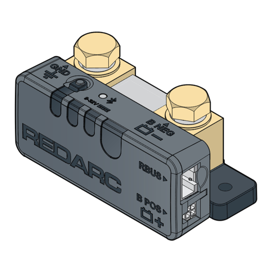
Page 4: Product Overview
Bluetooth � ® RedVision App� ® The Battery Monitor can be combined with REDARC R-Bus compatible products, including Get the Free the Manager with the RedVision Display� ® RedVision ® The Battery Monitor can also be used... -
Page 5: Wiring Diagram - Standalone Install
RedVision® App Refer to the Instruction Manual supplied with your Manager for detailed mounting and installation instructions� This wiring diagram shows a common/typical system configuration� If unsure, contact REDARC Technical Support for advice on your individual system requirements� See for more information on R-Bus system wiring. -
Page 6: System Planning
SYSTEM PLANNING WHAT YOU WILL NEED To mount, install and manage cabling of the Battery Monitor, the following common automotive electrical tools and consumables may be required: Heatshrink Cable cutters Cable ties ƒ ƒ ƒ Suitable cable lug Screwdriver / power drill P-Clips ƒ... - Page 7 CABLE REQUIREMENTS CAUTION: Cable sizes are specified by various codes and standards which depend on the type of vehicle the ƒ battery is installed in� Selecting the wrong cable size could result in harm to the installer or user and / or damage the Battery Monitor or other equipment installed in the system�...
-
Page 8: Installation - Mounting
Test that the R-Bus cable will comfortably reach between the Battery Monitor and the R-Bus input on a ƒ compatible REDARC product before installation (2 m (6'6") of cable length)� DO NOT mount with the RBUS and B POS ( +) sockets facing upwards, to prevent condensation/liquids ƒ... -
Page 9: Mounting Clearances
MOUNTING CLEARANCES MOUNTING INTERFERENCES Ensure the main housing of the Battery Monitor is clear from any protrusions (1 mm (0�04") clearance)� 1mm (0.04") Clearance MOUNTING IN AN ENCLOSED SPACE HOT SURFACE: High amperage loads connected to the Battery Monitor can cause the terminal/metal components to become extremely hot�... -
Page 10: Mounting Instructions
5/16" the Mounting Holes on the Battery Monitor� Two fasteners are required for mounting the Fasteners are Battery Monitor� REDARC recommend using not supplied M6 (1/4") to M4 (8#) fasteners with washers� If using countersunk fasteners, apply Ø 6.5 mm countersunk washers to avoid damaging the (1/4") -
Page 11: Installation - Wiring
Before making any connections to the Battery Monitor, assemble (or purchase) the Ground and Battery Negative cables with the appropriate size lug and heatshrink as shown below� REDARC recommends using heatshrink to protect the cable and lug connection from harsh environments, sharp edges and abrasion�... -
Page 12: Ground (Gnd) Cable Connection
GROUND (GND) CABLE CONNECTION Remove the M10 Bolt and washers from the Ground (GND ) terminal (1)� Then align the lug stud hole with the terminal and fasten using the flat washer, spring washer and bolt (2)� Torque to 20 Nm (14�7 ft-lbf)� Connect the Ground cable to a point that forms a common ground with all components in your setup (3)�... - Page 13 USING A TERMINAL BLOCK When connecting multiple loads to the Ground (GND ) terminal of the Battery Monitor, using a separate terminal block/earth busbar is recommended� Ensure the Ground cable connection to busbar is a sufficient size to suit your application� Terminal Block (not supplied) Installation —...
-
Page 14: Battery Negative (B Neg) Cable Connection
BATTERY NEGATIVE (B NEG) CABLE CONNECTION Remove the M10 Bolt and washers from the Battery Negative (B NEG –) terminal (1)� Then align the lug stud hole with the terminal and fasten using the flat washer, spring washer and bolt (2)� Torque to 20 Nm (14�7 ft-lbf)� Connect the Battery Negative cable to the auxiliary battery negative (–) terminal using appropriate fasteners (3)�... -
Page 15: R-Bus Cable Connection
Connect one end of the R-Bus cable to the RBUS socket on the Battery Monitor� Then, connect the other end of the cable to any available R-Bus (CAN) socket on the Manager or other compatible REDARC Products with an R-Bus system�... -
Page 16: Battery Sense Lead Connection
BATTERY SENSE LEAD CONNECTION Insert the Battery Sense Connector on the Battery Sense Lead into the B POS + socket on the Battery Monitor� Then, connect the Battery Sense Lug to the auxiliary battery positive (+) terminal using appropriate fasteners to secure� NOTICE: Do not fit the Battery Sense Lead between the auxiliary battery and lugs carrying high currents�... -
Page 17: Care And Maintenance
To avoid connections becoming loose, secure all cables to a fixed point close to the Battery Monitor ƒ (ideally within 200 mm (8"))� Cable ties, cable clips and P-clips are recommended� Flexible conduit can be used to manage and protect bundled cables� ƒ REDARC Manager Auxiliary (BMS1230S3) Battery AVOIDING WATER ENTRY Ensure that cables are routed with drip loops, this is to prevent moisture from running down the cables into the Battery Monitor�... -
Page 18: System Configuration
SYSTEM CONFIGURATION Once the Battery Monitor installation is complete, it needs to be configured using the RedVision Configurator App� The App defines the behaviours and operation of the Battery Monitor and informs the Battery Monitor of your auxiliary battery's specifications� If an R-Bus device is incorporated in your system, the RedVision Configurator App needs to be used in order to configure your entire system�... -
Page 19: Get The Redvision ® Configurator App
GET THE REDVISION CONFIGURATOR APP ® GET THE REDVISION CONFIGURATOR APP ® Download the free REDARC RedVision Configurator App to Configure the ® settings of your Battery Monitor using your smartphone via Bluetooth � ® The Configurator App and its interactions with the Battery Monitor have not been tested on all smartphone models� Visit the application pages with your App store to view compatibility details�... -
Page 20: Edit A Configuration
EDIT A CONFIGURATION 1. Open the RedVision Configurator App� 2. From the list, choose the configuration you want to edit� 3. Edit the configuration as required to suit your setup — remember to tap Save each time you make a change� 4. -
Page 21: Operation
OPERATION System testing is an important step to confirm the end-user experience of the configured system� Identifying and correcting errors is important before the system is operational and on-the-road� 1. Download and install the RedVision App� ® 2. Open the App and check that each connected device appears and functions as intended� 3. -
Page 22: Troubleshooting
SUBSEQUENT CONNECTIONS Once the smartphone has been paired with the Battery Monitor, it will automatically reconnect when the App is opened and the Battery Monitor is selected — Tap the Menu icon RedVision at the top right, then ® select the Battery Monitor from the list of devices� PAIR MULTIPLE SMARTPHONES The Battery Monitor can be paired to multiple smartphones;... - Page 23 To resolve installations where a Display is incorporated in your R-Bus system complete the following steps, in order, before directly contacting REDARC Tech Support or your local REDARC Distributor: 1. Check the R-Bus cable to make sure it is securely connected to the correct socket on each R-Bus input in your system�...
-
Page 24: Technical Specifications
TECHNICAL SPECIFICATIONS Specifications are subject to change without notice� GENERAL SPECIFICATIONS Main Unit Weight 355 g / 12�5 oz Main Unit Dimensions 120 × 52 × 45 mm / 4�7" × 2" × 1�8" Battery Sense Lead Length 1 m / 3�3' R-Bus Cable Length 2 m / 6�6' 25 mm... - Page 25 ELECTRICAL SPECIFICATIONS Operating Voltage Range 9 – 32 VDC Unit Operating Temperature −20°C to 60°C / −4°F to 140°F Power Mode / Device Mode Standalone With R-Bus Device Standby 2�4 mA – 3 mA 2�4 mA – 3 mA Normal 7 mA – 14 mA 12 mA – 18 mA Voltages Specified are ±...
- Page 26 COMPLIANCE FCC ID 2BAH6-SU601 30290-SU601 Standards Internal Transmission Notice 1. WARNING: Any changes or modifications not expressively approved by the grantee could void the user's authority to operate this equipment. 2. Note: This equipment has been tested and found to comply with the limits for a Class B digital device, pursuant to part 15 of the FCC Rules�...
-
Page 27: Warranty
All rights reserved� | REDARC® and THE POWER OF REDARC® are trademarks of REDARC Electronics Pty Ltd� Bluetooth® word mark and logos are registered trademarks owned by Bluetooth SIG, Inc� and any use of such marks by REDARC is under... - Page 28 Tech Support 1300 REDARC (1300-733-272) Australia +61 8 8322 4848 New Zealand +64 9 222 1024 UK & Europe +44 (0)20 3930 8109 +1 (704) 247-5150 Canada +1 (604) 260-5512 Mexico +52 (558) 526-2898 redarcelectronics.com INST239-4...
Need help?
Do you have a question about the BSEN500 and is the answer not in the manual?
Questions and answers