
Subscribe to Our Youtube Channel
Related Manuals for Riello MultiCOM 421


Summary of Contents for Riello MultiCOM 421
- Page 3 INTRODUCTION Thank you for choosing our product. The accessories described in this manual are of the highest quality, carefully designed and built in order to ensure excellent performance. This manual contains detailed instructions on how to install and use the product. This manual must be stored in a safe place and CONSULTED BEFORE USING THE DEVICE for proper usage instructions as well as maximum performance from the device itself.
- Page 4 INDEX PRESENTATION N THE BOX XTERNAL VIEW PROFINET GATEWAY CONNECTORS AND LEDS PROFINET CONNECTOR OWER CONNECTOR COM 302 ULTI CONNECTOR TATUS MULTICOM 302 JUMPER AND DIP SWITCHES SETTINGS INSTALLATION COM 302 ↔ PROFINET DP G ONNECTION CABLE ULTI ATEWAY DIN- RAIL MOUNTING PROFINET I/O DATA...
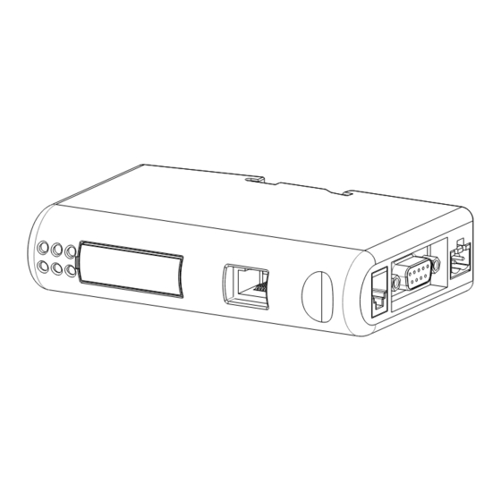
- Page 5 PRESENTATION MultiCOM 421 allows to integrate the management and monitoring of the UPS into a PROFINET network. N THE BOX MultiCOM 302 board PROFINET Gateway Connection cable between MultiCOM 302 and PROFINET Gateway XTERNAL VIEW PROFINET Connector Status LEDs Reserved...
- Page 6 PROFINET GATEWAY CONNECTORS AND LEDS PROFINET CONNECTOR Signal Housing Cable Shield Termination Termination Termination Termination OWER CONNECTOR Description +24 VDC (300 mA required) Note: no power supply is provided with the device. COM 302 ULTI CONNECTOR Description 1, 2, 3, 4, 6, 7 Signal Ground RS485+ RS485-...
- Page 7 TATUS Indication Meaning Not online Online, connection with IO established, 1 - Communication Green IO controller in run state Status Online, connection with IO established, Flashing Green IO controller in stop state No power / Not initialized Green Initialized, no errors 1 Sequential Green Blink Diagnostic data available Used by engineering tool to identify the...
-
Page 8: Installation
INSTALLATION Remove the cover of the UPS expansion slot by removing the two retaining screws. Insert MultiCOM 302 in the slot. Fix the cover provided using the screws previously removed. Connect the PROFINET Gateway to the MultiCOM 302 using the cable provided with the device. NOTE: if necessary, you can also use another cable realized in accordance with the specifications (see Connection cable MultiCOM 302 ↔... -
Page 9: Profinet I/O Data
PROFINET I/O DATA The UPS’s values are presented to the Master PLC/Controller as easily processed I/O data. INPUT DATA BYTE # REGISTER # DESCRIPTION UNIT High States / alarms 1 States / alarms 2 Charge% Autonomy Minutes RESERVED Load phase L1 Load phase L2 Load phase L3 Input voltage (Ph-N) V1... - Page 10 INPUT DATA BYTE # REGISTER # DESCRIPTION UNIT High RESERVED Battery temperature °C Power 1 temperature °C Power 2 temperature °C Power 3 temperature °C Input current phase L1 A/10 Input current phase L2 A/10 Input current phase L3 A/10 RESERVED RESERVED RESERVED...
- Page 11 STATES / ALARMS 2 BIT # DESCRIPTION 15 (MSB) UPS failure [0=NO / 1=YES] Alarm overload [0=NO / 1=YES] Alarm temperature [0=NO / 1=YES] Input mains present [0=NO / 1=YES] 0 (LSB) OUTPUT DATA BYTE # REGISTER # DESCRIPTION UNIT High Command Code: 0 (0x0000) →...
- Page 12 0MNACCMCAENUA...
Need help?
Do you have a question about the MultiCOM 421 and is the answer not in the manual?
Questions and answers