
Subscribe to Our Youtube Channel
Related Manuals for Riello N35


Summary of Contents for Riello N35
- Page 1 Installation, use and maintenance instructions Riello Gateway CODE LMV3, LMV5, Array, Massimo, Picollo 20141213, 20141214 01/2019...
-
Page 2: Table Of Contents
CONTENTS TABLE OF CONTENTS BURNER(S)/BOILER(S) SETUP 1.1 PRODUCT USAGE 1.2 FIELD DEVICE CONNECTIONS 1.3 SETTING UP FIELD CONTROLLER(S) 1.3.1 SETTING UP THE ARRAY BOILER CONTROLLER(S) 1.3.2 SETTING UP THE LMV3 AND RWF CONTROLLER(S) 1.3.3 SETTING UP THE LMV5 CONTROLLER(S) GATEWAY SETUP AND ELECTRICAL CONNECTIONS 2.1 GATEWAY BREAKDOWN 2.2 DIP SWITCHES 2.2.1 A DIP SWITCHES-BAS SIDE MAC ADDRESS (ONLY FOR BACNET MSTP) -
Page 3: Burner(S)/Boiler(S) Setup
BURNER(S)/BOILER(S) SETUP BURNER(S)/BOILER(S) SETUP 1.1 PRODUCT USAGE CASE 1 (Array Boiler): The gateway can connect with up to 8 Array boilers…This is 1 boiler MODULES– There are 8 modules within this one boiler Note: Number of modules depends on the boiler model. Ex. Array 1000 has 2 modules, Array 3000 has 6 modules, etc. -
Page 4: Field Device Connections
Please see Array Control System manual *** AL Bus for cascade control is on a separate daisy chain. Please see Array Control System manual *** Please see job specific Riello burner drawings for linkageless LMV3, LMV5 burners... -
Page 5: Setting Up Field Controllers
BURNER(S)/BOILER(S) SETUP 1.3 SETTING UP FIELD CONTROLLERS 1.3.1 CASE 1: SETTING UP THE ARRAY BOILER CONTROLLER(S) *** Important : There is nothing the BAS technician needs to change with respect to the Modbus side of the boilers. Modbus addressing is automatically set up through the cascade 1.3.2 CASE 2: SETTING UP THE LMV3 AND RWF55 CONTROLLER(S) >... -
Page 6: Gateway Setup And Electrical Connections
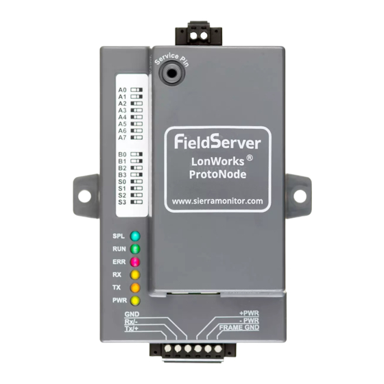
GATEWAY SETUP AND ELECTRICAL CONNECTIONS GATEWAY SETUP AND ELECTRICAL CONNECTIONS 2.1 GATEWAY BREAKDOWN... -
Page 7: Dip Switches
GATEWAY SETUP AND ELECTRICAL CONNECTIONS 2.2 DIP SWITCES 2.2.1 A DIP SWITCHES - BAS SIDE MAC ADDRESS (ONLY FOR BACNET MS/TP) - Page 8 GATEWAY SETUP AND ELECTRICAL CONNECTIONS 2.2.1 A DIP SWITCHES - BAS SIDE MAC ADDRESS (ONLY FOR BACNET MS/TP)
-
Page 9: B Dip Switches-Profile Selection
GATEWAY SETUP AND ELECTRICAL CONNECTIONS 2.3.2 B DIP SWITCHES—PROFILE SELCTION For example: On page 3, case 2 is chosen. This means you have an LMV3 on the burner and the BAS network is decided to communicate through BACnet MS/TP. You would choose the 10th profile, using dip switches B0-”ON”, B1-”OFF”, B2-”OFF”, B3-”ON”. -
Page 10: Setting Up Your Desktop
GATEWAY SETUP AND ELECTRICAL CONNECTIONS 2.4 SETTING UP YOUR DESKTOP 2.4.1 DISCOVERING A DEVICE 1. Please download fieldserver toolbox from the following link: https://www.sierramonitor.com/content/fieldserver-toolbox-0 2. Open toolbox application, at this point the toolbox will discover the gateway connected to your laptop 2.4.2 SETTING UP YOUR LAPTOP TO CONNECT TO THE GATEWAY Assuming the gateway has the following default IP address: 192.168.1.24 and Subnet Mask: 255.255.255.0….. -
Page 11: Changing The Gateway Ip
GATEWAY SETUP AND ELECTRICAL CONNECTIONS Step 3: Right click on “Internet Protocol Version 4(TCP/IP/IPV4)” Step 4: Change IP and Subnet Mask to match the network of the gateway. 2.5 CHANGING THE GATEWAY IP Step 1: Open up your internet browser, enter IP address of gateway, and click on “Diagnostics &... - Page 12 GATEWAY SETUP AND ELECTRICAL CONNECTIONS 2.5 CHANGING THE GATEWAY IP Step 1: Open up your internet browser, enter IP address of gateway, and click on “Diagnostics & Debugging” at the bottom right hand side of the page. Step 2: On the Nav tree, click “Setup”, then “Network Settings”...
-
Page 13: Troubleshooting
TROUBLESHOOTING TROUBLESHOOTING 3.1 GATEWAY LIGHTS SPL - Will light if the gateway is offline. RUN - Will start flashing 20 seconds after power indicating normal operation. ERR - Will go solid 15 seconds after power up. It will turn off after 5 seconds. A steady red light indicates that there is an error. -
Page 14: Accessing The Gateway To Troubleshoot
TROUBLESHOOTING 3.2 ACCESSING GATEWAY TO TROUBLESHOOT Troubleshooting steps after setup, if red light is flashing or gateway is not communicating: Is ERR light flashing? If ERR light is NOT flashing then: Connect to the gateway from your internet browser by entering the gateway IP address (see section 2.4). -
Page 15: Object Tables
OBJECT TABLES OBJECT TABLES 4.1 LMV3 BURNER(S) TABLE BACnet MS/TP - Default: Baud Rate - 38400 (adjustable through internet GUI) , Parity - none, Data Bits - 8, Stop Bits - 1, Node ID - 1547 (adjustable through internet GUI) , Max Master - 127, and MAC address is set through dip switches A. -
Page 16: Lmv5 Burner(S) Table
OBJECT TABLES 4.2 LMV5 BURNER(S) TABLE BACnet MS/TP - Default: Baud Rate - 38400 (adjustable through internet GUI) , Parity - none, Data Bits - 8, Stop Bits - 1, Node ID - 1547 (adjustable through internet GUI) , Max Master - 127, and MAC address is set through dip switches A. -
Page 17: Array Boiler(S) Table
OBJECT TABLES 4.3 ARRAY BOILER(S) TABLE BACnet MS/TP - Default: Baud Rate (adjustable through internet GUI) - 38400, Parity - none, Data Bits - 8, Stop Bits - 1, Node ID - 1547(adjustable through internet GUI) , Max Master - 127, and MAC address is set through dip switches A. - Page 18 OBJECT TABLES 4.3 ARRAY BOILER(S) TABLE...
- Page 19 OBJECT TABLES 4.3 ARRAY BOILER(S) TABLE...
-
Page 20: Array State/Error Table
OBJECT TABLES 4.3.1 ARRAY STATE/ERROR TABLE STATE TABLE (Boiler(x)Mod(x)_State) Profile DESCRIPTION INITIALIZATION VARIABLES FOR INITIALIZATION RESET (START-UP) STATE RESET RESET (START-UP) STATE STANDBY STANDBY 3or4 PRE-PURGE PRE-PURGING 5or6 PRE-IGNITION PRE-IGNITION FLAME PROVING FLAME PROVING 8or9 BURN BURN 10or11 POST PURGE POST-PURGE ERROR ERROR... - Page 21 OBJECT TABLES 4.3.1 ARRAY STATE/ERROR TABLE ERROR TABLE (Boiler(x)Mod(x)_Error BLOCKING Code) WD_ERROR_RAM WD_ERROR_RAM E2PROM_READ_ERROR WD_ERROR_STACK IGNIT_ERROR WD_ERROR_REGISTER GV_RELAY_ERROR WD_ERROR_XRL SAFETY_RELAY_ERROR HIGH_TEMP_ERROR BLOCKING_TOO_LONG REFHI_TOO_HIGH FAN_ERROR_NOT_RUNNING REFHI_TOO_LOW FAN_ERROR_TOO_SLOW REFLO_TOO_HIGH FAN_ERROR_TOO_FAST REFLO_TOO_LOW RAM_ERROR REFHI2_TOO_HIGH WRONG_EEPROM_SIGNATURE REFHI2_TOO_LOW E2PROM_ERROR REFLO2_TOO_HIGH STATE_ERROR REFLO2_TOO_LOW ROM_ERROR FALSE_FLAME APS_NOT_OPEN LOW_WATER_PRESSURE_ERROR APS_NOT_CLOSED LOW_WATER_PRESSURE_SENSOR...
- Page 22 OBJECT TABLES 4.3.1 ARRAY STATE/ERROR TABLE T_SELECTION1_OPEN T_SELECTION2_OPEN T_SELECTION3_OPEN T_OPTIONAL1_OPEN T_OPTIONAL2_OPEN T_AMBIENT_OPEN T_CHIMNEY_CLOSED T_EXCHANGE1_CLOSED T_EXCHANGE2_CLOSED T_SELECTION1_CLOSED T_SELECTION2_CLOSED T_SELECTION3_CLOSED T_OPTIONAL1_CLOSED T_OPTIONAL2_CLOSED T_AMBIENT_CLOSED WD_CONFIG_ERROR FLUE_PRESSURE_ERROR AIR_DAMPER_ERROR T_SECONDARY_SUPPLY_OPEN T_SECONDARY_RETURN_OPEN T_SECONDARY_SUPPLY_CLOSED T_SECONDARY_RETURN_CLOSED FILL_WARNING FLUE_BLOCKED LOWEXFLOW_PROTECTION WARNINGS CC_LOSS_COMMUNICATION CC_LOSS_BOILER_COMM OUTDOOR_WRONG T_SYSTEM_WRONG T_CASCADE_WRONG NOTHING IS WRONG...
Need help?
Do you have a question about the N35 and is the answer not in the manual?
Questions and answers