Advertisement
Quick Links
Advertisement

Related Manuals for C-Tech 16-T0012/P


Summary of Contents for C-Tech 16-T0012/P
- Page 1 Dynamic Cone Penetrometer 16-T0012/P...
-
Page 2: Table Of Contents
CONTENTS Introduction ..............................1 Security ................................1 III. Description ..............................3 IV. Operation .................................5 Technical data .............................. 10 VI. Maintenance ..............................11 Warranty Card ..............................15 Packing List ................................16... -
Page 3: Introduction
I. Introduction Below you will find important information on how to use the pneumatic ram probe 16-T0012/P, referred to in the further text 16-T0012/P. A suitable compressor is required to operate the 16-T0012/P. This compressor must be designed for the operation of the pneumatic ramming probe and have the required performance data. - Page 4 The user of the 16-T0012/P must wear the following protective clothing: 1. Helmet 2. Hearing protectors Stay at the device Maintain a safety distance of at least 1 meter to the 16-T0012/P in operation to prevent injury due - 2 -...
-
Page 5: Description
A list of the necessary testing and maintenance work can be found in chapter 6.1. In order to ensure safe operation of the 16-T0012/P, you are obliged to have the work carried out by a qualified person in accordance with the maintenance list. - Page 6 Name Name Name Name Cylinder handle B type pin Round nut bolt Briquetting handle Circlip Briquetting 20kg hammer Connector piston Cylinder Flat end Trachea joint Nuts Scope of delivery and accessories Packing List 1 10kg weight and cylinder with handle ...
-
Page 7: Operation
1 set extractor 2 5CM cone heads 2 10CM cone heads 20 10CM disposable cone heads 1 M8 Allen wrench 1 set of safety rod device Safety components Safety pin with cotter pin to secure the ram probe on the striker. ... - Page 8 Set up Screw the striking piece onto the probe rod and place the 16-T0012/P with the anvil on the striking piece. Insert the safety bolt through the holes in the anvil and striker and secure it with the split pin.
- Page 9 Push open pipe Support socket for auxiliary safety rod, starting at a end over the safety bolt of right angle. the ram probe secure it with a pin. Regulating valve, inserted in the hose section of the safety rod. DPL operation Auxiliary safety bar (2-man operation recommended for probing approach with additional weight)
- Page 10 Add additional weight with the side of the larger inner diameter forward via the ram probe and place on the impact socket of the 16-T0012/P. Slide the fastening clamp all the way to the additional weight and tighten it well. Make sure that the blow-off hole, which is now behind the additional weight, remains free.
- Page 11 WARNING! Keep a safety distance of at least 1 meter from the 16-T0012/P in operation to prevent injuries caused by the device falling down (e.g. in the event of a break); a blow to the head or body can lead to serious injuries.
-
Page 12: Technical Data
Connection coupling turned inwards in a protected position. V. Technical data Specifications Length 850 mm Max diameter 102 mm (without additional weight) Total weight 130 kg Ramm weight 10 kg Additional weights 1 x 20 kg for DPM, optional Drop height 0.5 m Required air volume max. -
Page 13: Maintenance
VI. Maintenance Below you will find information on maintenance and maintenance of the 16-T0012/P. Read this section carefully as inadequate care and inadequate maintenance can result in damage. NOTE: Always turn off the compressed air source or unplug the hose line before performing maintenance or cleaning. - Page 14 3. The proper function can be restricted by using an unsuitable lubricating oil (resin spray oils ) or by improperly placing the ram probe in the field. Proceed as follows to dismantle and clean the ram probe: ①. Senkrecht vertically. Ventilschaft Traverse with Screws M6 x 25 (medium-tight glued)
- Page 15 control head upwards out of the cylinder barrel. ④. To dismantle the cylinder tube, the locking circlip and the inner assembly O-ring are now removed from the piston rod and the cylinder tube is pulled off upwards. The piston is now in the cylinder barrel and is carefully pushed out with a non-metallic rod (e.g.
- Page 16 Gap 1 – 2 mm Note: all the above showing pics and sketchs are for reference only - 14 -...
-
Page 17: Warranty Card
Warranty Card Produce Name Dynamic Cone Penetrometer Date Of Manufacture Produce Code 16-T0012/P Inspectors Warranty Period The warranty period is 1 year from the date of purchase Maintenance Record Form Date Fault Conditions Signature Remarks - 15 -... -
Page 18: Packing List
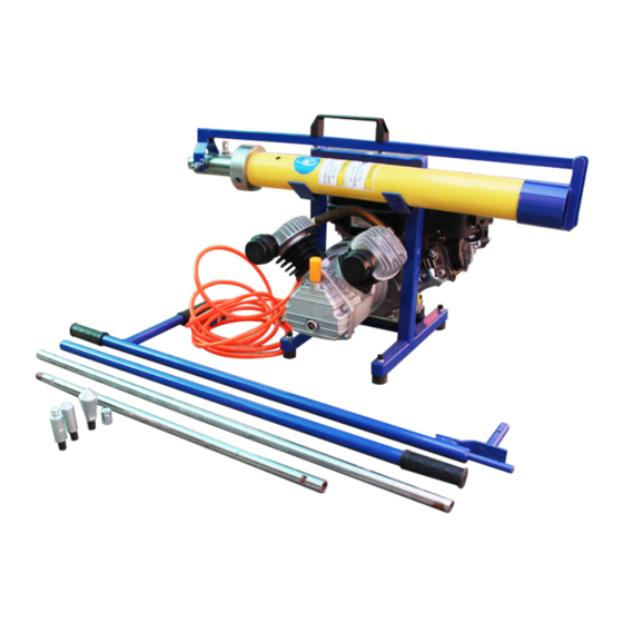
Packing List Item. Label Number 4-stroke gasoline engine and air compressor with hose connector and bracket 10kg weight and cylinder with handle Additional weight 20kg Air hose Probe rod φ22*1000mm, with scale mark every 100mm user's Guide 19mm spanner for 22mm probe Threaded joint M16 Extractor cone head... - Page 19 - 17 -...
Need help?
Do you have a question about the 16-T0012/P and is the answer not in the manual?
Questions and answers